

1. Introduction#
1.1. Background: Fine Element Method#
A designer will always want to know whether the device or structure devised by him/her will be able to perform the set task. To find out, a prototype can be built and tested. If it is not good, we build a new one and see what it does. Very time-consuming of course and (because of this) very expensive. It is much better (faster, cheaper) to try to predict the behaviour of the structure before anything is built. This forecasting can be done through sensible reasoning (”If I push here, it will go down there”). This is obviously not good enough. If we want to accurately predict, then we have to calculate. We have to model the construction (on paper) and check what the load is. It is then possible to predict the behaviour by solving a number of mathematical equations. The preparation of these equations (the mathematical model) is the subject of mechanics. You can solve this with techniques that mathematicians have devised for us.
Easier said than done, because the mathematical equations are in most cases rather complex. So difficult that an exact solution is impossible (even for mathematicians) or can only be derived by monks (m/f). Fortunately, this problem is no longer there since we have computers. These contemporary monks can be of excellent service to us when modelling constructions and performing complex calculations. It has been necessary to develop special numerical methods that computers can use.
In mechanical engineering, the finite element method (FEM) is the most commonly used. Special FEM programs have been developed and are for sale. FEM software is currently very advanced. Complex models can be made and (quickly) calculated. The predicted behaviour can be displayed visually very realistic, which we call simulation.
This manual describes how truss structures can be modelled and analysed. In that case, modelling is simple and can partly be done by hand. The same applies to the modelling of structures that are made up of beams, which is also described in this manual.
1.2. MARC/Mentat#
We use the FEM program MARC in our department, which is an abbreviation from Marc Analysis and Research Corporation. MARC is the calculation program and thus solves the aforementioned equations. Modelling the construction is done with the Mentat program. This program is also used to view the results of the calculations performed by MARC. Such a program as Mentat is called a pre- and postprocessor.
This brief manual will guide you through the steps required to perform a FEM simulation. In this way you will learn to work with Mentat (and MARC) and gain some knowledge (refresh) on mechanics and the finite element method.
In the following paragraphs, first a brief description of Mentat and MARC follows. A detailed description can be found in the manuals associated with these programs, which can be consulted directly by pressing help. Detailed information about the possibilities of MARC are described in Volume A, the User Information. All available elements are described in Volume B, the Element Library. With Mentat the model is created with the final result a MARC input file with extension .dat. The commands in this file with all the options that go with it are described in detail in Volume C, Program Input. It is possible to expand the MARC program with your own software, written in the programming language Fortran and in MARC terminology called user subroutines. What possibilities there are and how to use them is described in Volume D, User Subroutines and Special Routines. Finally there is a Volume E with Demonstration Problems.
1.3. Mentat#
When Mentat is started, we see a screen that has been arranged in a certain way, as shown in the figure below. In some parts we see a number of buttons which we will soon click with the left-mouse button.
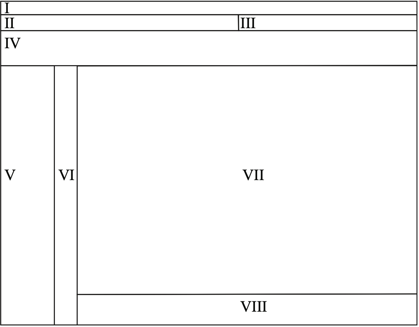
Fig. 1.14 Mentat screen arrangement#
Section |
|
|---|---|
Ⅰ |
This is the main navigation menu (main). |
Ⅱ |
Here are buttons with which new files can be created/saved, actions can be undone, and we can manipulate the view. |
Ⅲ |
The analysis type can be chosen here. Throughout the training, it must remain on structural. |
Ⅳ |
This section contains the so-called main menu. With the tabs and sub-selection options, buttons and pull-out menus are available in V so that we can create the model and change the created model again. |
Ⅴ |
With the buttons and pull-down menus in this part (the dynamic menu), which become visible through the selections we make in IV, we can finally make the model. |
Ⅵ |
Here we can execute list specifications, which will be discussed later in the training. |
Ⅶ |
This is the model screen where the created model is displayed. |
Ⅷ |
In the command screen we enter the data if Mentat requests it. |
In the examples that will be discussed below, we will walk step by step through the various menus. We use the following fonts for the different names and buttons:
Feature |
Description |
|---|---|
TAB NAME |
(grey blue) The name of the tab in main menu (Ⅵ). |
SELECT (location) |
(green) By clicking on these buttons with the left-mouse button a new menu appears in the dynamic menu (Ⅴ). If necessary, the name of the location on the specific tab is displayed between brackets. |
TOGGLE BUTTON |
(blue) When clicking on these buttons, a command is issued (e.g. SAVE), one or two possible settings are chosen (toggle action) or a choice is made from a list of possibilities. In the latter case, additional data may sometimes have to be entered in the command window. |
mentat-text |
(in command-window) Mentat often asks for input. In many cases, it is not necessary to enter it via the keyboard because buttons can be used. |
user-text |
(in command-window) These are usually data that the user must enter via the keyboard. |
menu-text |
(in menus) These are items that can be selected from a list that appears in a menu. Selection is done with the left-mouse button. |
mouse-button-click |
lm : left-mouse button; is used to click buttons and to select items. |

Click on  to make the drop-down menu.
When commands have to be executed via the main navigation menu (Ⅰ) they will be displayed in the manual as: selection→selection→ …
When we start Mentat, the program is automatically initialized, which means that certain settings (colours, parameters, dimensions) have their default values. All kinds of settings will be changed during use. If we want to restore the initial settings, we type in the command screen (Ⅷ) the following commands:
*reset
*reset_view
both followed by enter to confirm or via the main navigation menu:
tools → program settings → RESET PROGRAM → OK
view → view control → RESET VIEW → OK