
1. Introduction, general concepts and equilibrium#
1.1. general concepts and equilibrium#
Book: Introduction Chapter 1, Sections 1.1 and 1.2.
Statics: Acceleration of the body is zero or negligible.
Mechanics of rigid bodies: Only the equilibrium of forces and moments of the structure is important. The strength (maximum load) and stiffness (resistance to deformation) are assumed to be infinite and therefore do not play a role.
Mechanics of deformable bodies (mechanics of materials): Deformation of the body needs to be taken into account. Strength and stiffness is finite and dependent on the material and shape of the structure. If the deformation of the body fully recovers after removing the load, it is called elastic deformation. However, if (part of) the deformation persists we have plastic deformation.
Too large deformation and fracture are examples of failure of a structure.
A force can be interpreted as an interaction between bodies that can result in acceleration and/or deformation of the bodies (by contact or by action at a distance, such as from electric, magnetic or gravity fields). Forces are vectorial quantities, i.e. they both have a magnitude and a direction. The usual mathematical rules for vector addition, subtraction and multiplication with a real number are assumed to be valid.
Unit of force: \(\textrm{N}\) (newton).
Scalars: quantities that only have a magnitude.
A point force on a structure is the resultant of a distribution of forces. In Fig. 1.1, the simplification of a point force is shown as an idealization of a realistic scenario.
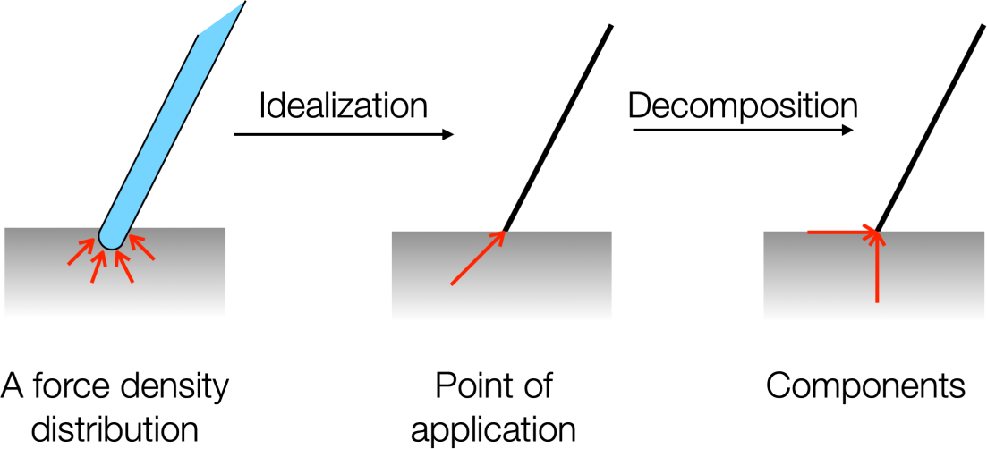
Fig. 1.1 The point source is visualized in three steps: realistic, idealized, and decomposed.#
A body is in equilibrium if inertia (mass \(\times\) acceleration) can be neglected (both with respect to translational and rotational motion).
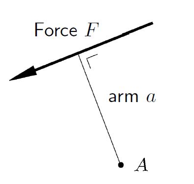
The moment of a force relative to a point is the product of the magnitude of the force and the perpendicular distance of the point to the line of action of the force. The moment is a vectorial quantity and therefore has a magnitude and a direction. The direction is determined by the right-hand rule.
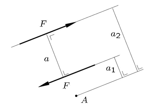
A couple consists of two parallel forces of equal magnitude, but having an opposite direction. The moment of the couple is independent from the point chosen to determine the moments of the individual forces.
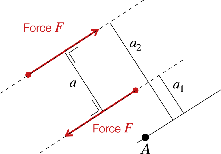
Fig. 1.2 A couple of forces. \(A\) is the reference point, \(a_1\) and \(a_2\) are the respective distances from \(A\) to the forces, and \(a\) is the distance between the forces.#
Fig. 1.2 shows a couple, the two parallel forces. The reference point is taken as \(A\) with distances \(a_1\) and \(a_2\). The forces are separated by distance \(a\).
Restriction to planar structures: All forces are in the plane of the structure and all moments are perpendicular to that plane. A moment can be reduced to a scalar value, where the sign is determined by the choice of the positive rotational direction.
The three laws of Newton (and Euler) are, in short:
No external forces and moments = no acceleration of a body.
\(\textrm{Force}=\textrm{mass} \times \textrm{acceleration}\), for point masses and the center of mass of a body.
\(\textrm{Moment}=\textrm{angular mass} \times \textrm{angular acceleration}\).Action is reaction.
For a body in equilibrium this reduces to the equilibrium equations:
Sum of all forces is zero.
Sum of all moments is zero. This is valid for any point used for computing the moments.
Action is reaction.
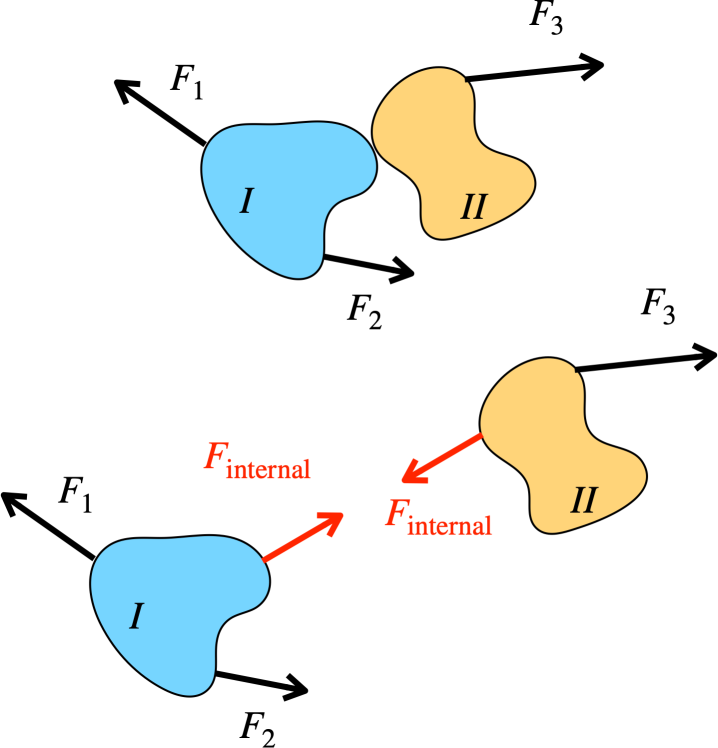
Fig. 1.3 The isolation of parts from a body/structure such the internal forces of the body can be visualized.#
For a body in equilibrium, any isolated part of that body will be in equilibrium as well. Isolating a part of a body from its environment and drawing all forces acting on that part is called drawing a free body diagram. This requires virtually cutting through some members of the body/structure and internal forces at the cut become external forces on the isolated parts. Application of Newton’s third law is essential here. Internal forces arise (“are released”) when isolating a part of the body/structure from the rest of body/structure. Fig. 1.3 above shows this process.
If three nonparallel forces are acting on a body (or an isolated part of the body), the forces form a closed triangle, because the resultant force is zero. This can be seen in the right side figure of Fig. 1.4 below.
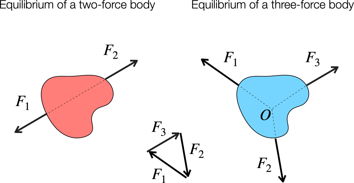
Fig. 1.4 Two and three force body systems.#
For planar structures in equilibrium, and for every arbitrary isolated part of such a structure, we have three independent equilibrium equations. For example, the sum of forces in two different directions and sum of moments with respect to a fixed chosen point are zero. Another possibility is to use that the sum of moments is zero with respect to two different points and a sum of forces is zero in a single direction. The latter direction should not be taken perpendicular to the line connecting the two moment points. Otherwise the three equations will be dependent and no solution is possible. A third possibility is to use three different moment points. However, these points should not belong to the same line (colinear). Otherwise, again the three equations will be dependent and no solution is possible. Which choice is the best depends, and only doing many exercises will give you enough experience to make a smart choice. A smart choice of the fixed point for the moment equation is often the point for which the moment is zero for as many unknown forces as possible.
If we can solve all unknown forces in the structure by using only the equilibrium equations, we say the structure is statically determinate. Example 1.1. below will show simple example of a statically determinate system.
Fence post
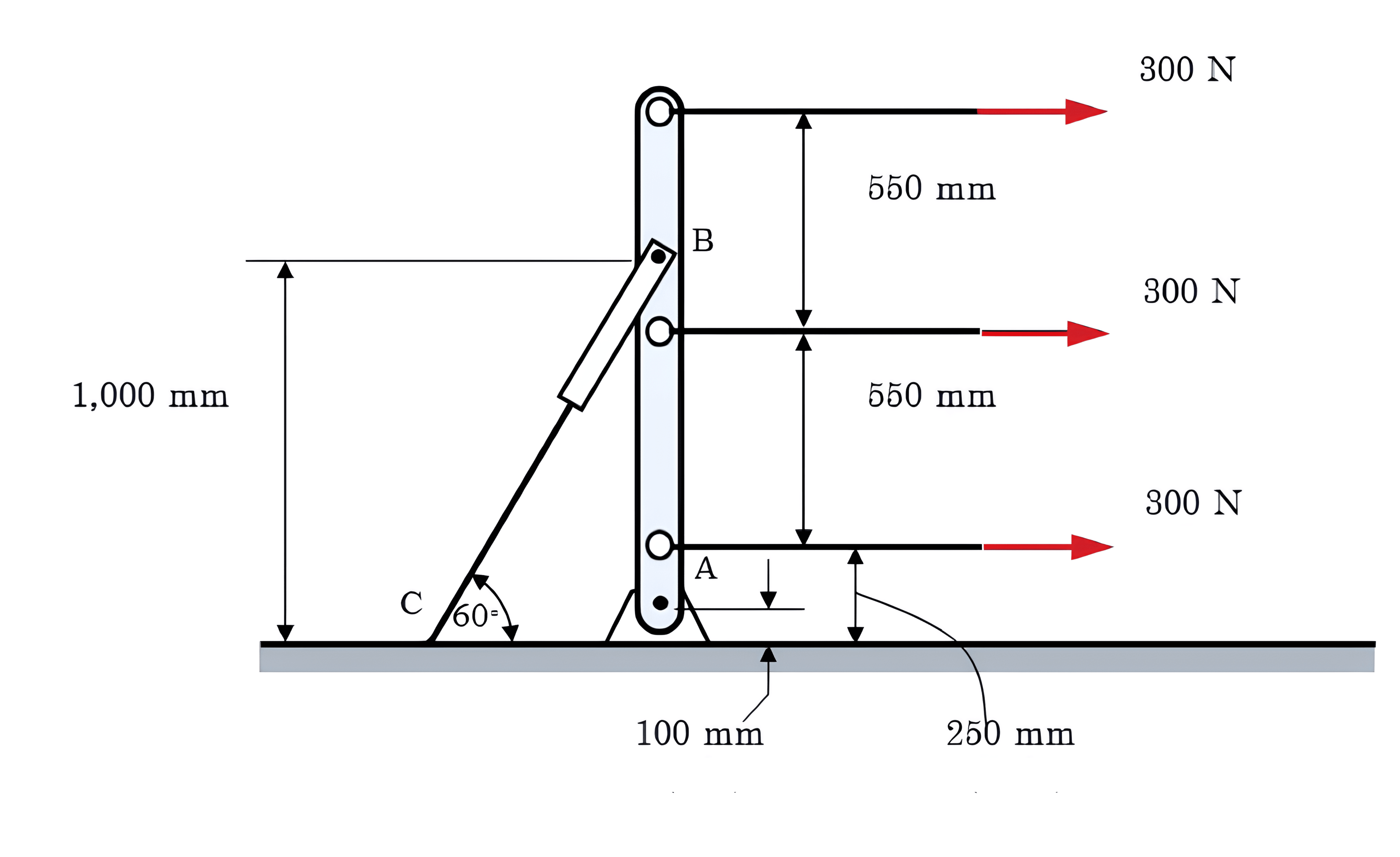
Fig. 1.5 Fence post schematic#
Consider part of a fence shown in Fig. 1.5. The vertical fence post is free to rotate about a pinned joint at \(A\) and is secured to the ground by the light stay wire \(BC\), which is pinned to the post at \(B\). Three horizontal wires are attached to the post, and the tension in each is known to be 300 N. Find the tension in the stay \(BC\) and the horizontal and vertical components of the reaction force acting on the post at \(A\).
Solution
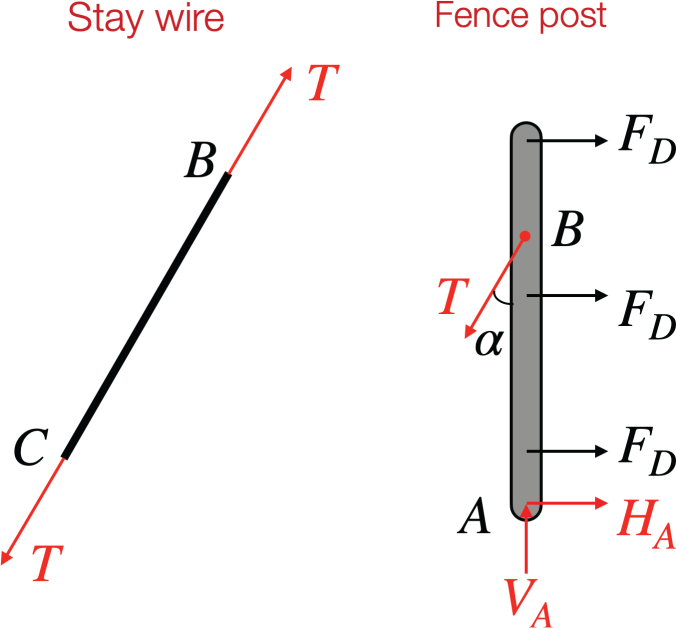
Fig. 1.6 Necessary body diagrams of stay wire and fence post.#
For our present purposes, we assume that friction forces at the joints are negligible and that no moments are transmitted. Our model of the problem, expressed in the form of free body diagrams for the stay wire and fence post, is therefore as shown in Fig. 1.6. The tension in the wire is shown as \(T\), while the horizontal and vertical reaction components acting on the post at \(A\) are shown as \(H_A\) and \(V_A\), respectively. The free body diagram for the stay wire, Fig. 1.6 (left), is a very simple one. With only two forces acting (since the wire is described as light, we neglect its weight), these must act along the straight wire in opposite directions. By geometric arguments we find that \(\alpha\) is \(30°\). In order to solve the problem, we first write down equations of equilibrium for the external forces acting on the fence post as shown in Fig. 1.6 (right).
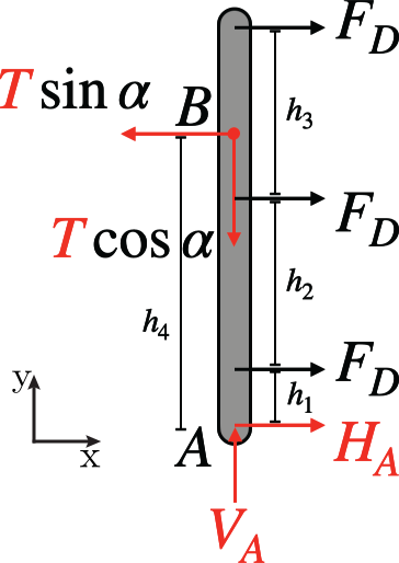
Fig. 1.7 Worked out fence post for equations of equilibrium.#
Fig. 1.7 shows that the decomposition of the tension. \(h_{1,2,3,4}\) are the provided values that can be read from Fig. 1.5. This provides us with enough information to set up the equations of equilibium given by
Here the equations of motions in the horizontal and vertical direction are given as well as the clockwise moment. The tension and horizontal and vertical reaction components can now be calculated:
It is a good idea to check our results, when filling in our found values we get
Thus we have verified that our found values correspond to our moment. We can get more insight into our problem by not filling in the numerical values immediately. With
\(H_A\) can be written as
We now have the tools to check if the dimensions of the tension make sense:
The dimensions correspond with what we would expect. With this information we can gain several other insights:
as \(\alpha \uparrow\), \({\color{red} T} \downarrow\)
\(\color{red}H_A\) is independent of \(\alpha\)
Which \(h_4\) gives \({\color{red}H_A} = 0\)? (Answer: \(700 \rm \,mm\))
Sometimes smart choices for the directions of the equilibrium of forces lead to a much easier system to solve.
A structure where the number of unknown forces is larger than the number of (usable) equilibrium equations is called statically indeterminate. The unknown forces can only be found by taking the deformation of the structure into account. This will be the topic of Chapter 4.