
2. Trusses#
Book: Introduction Chapter 2 and Section 2.1.
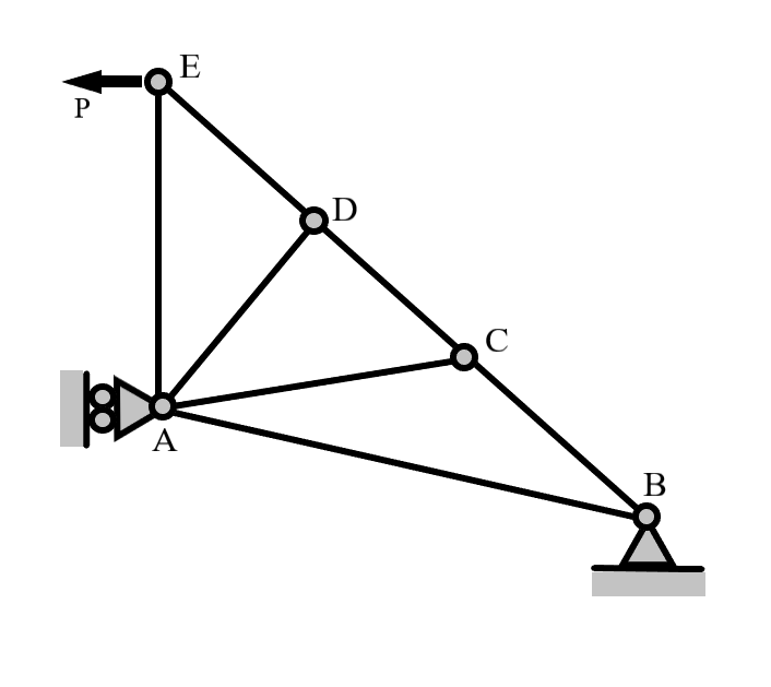
A truss is a structure consisting of slender members that are jointed together at their ends. The joints can be modelled as frictionless pin (2D) or ball-socket (3D) connections. Since the members can only transfer forces (no moments), they are also called “two-force members”. Fig. 2.1 shows a visualization of a two forc member below.
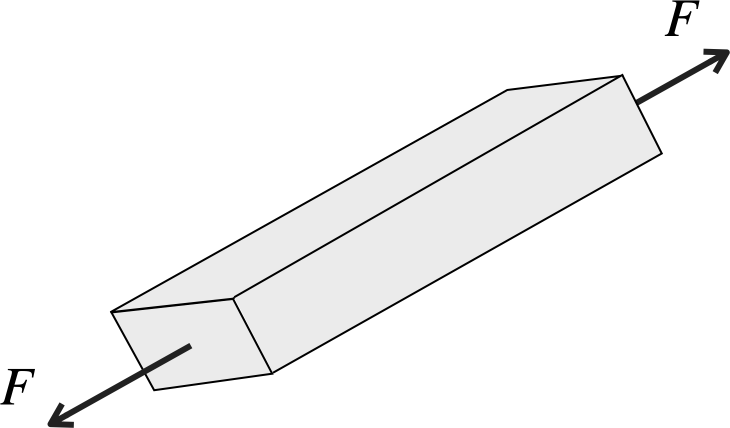
Fig. 2.1 A two force member body.#
\(F>0\): member in tension
\(F<0\): member in compression
\(F=0\): zero force member
2.1. Planar or 2D trusses (Pin-jointed Structures)#
Two-dimensional trusses are called pin-jointed structures. The members are connected at the joints and only forces (no moments) can be transferred in these joints. The members itself can transfer only axial (normal) forces. In practice the joints do not have to be real frictionless pin-joints as long as they can be modelled as such. A truss is always a model (an approximation) of the real structure. Various designs exist for connecting slender members in order to be able to model the structure as a truss (no transfer of moments between members). Below in figures Fig. 2.2 and Fig. 2.3 the dynamics of a pin joint can be seen.
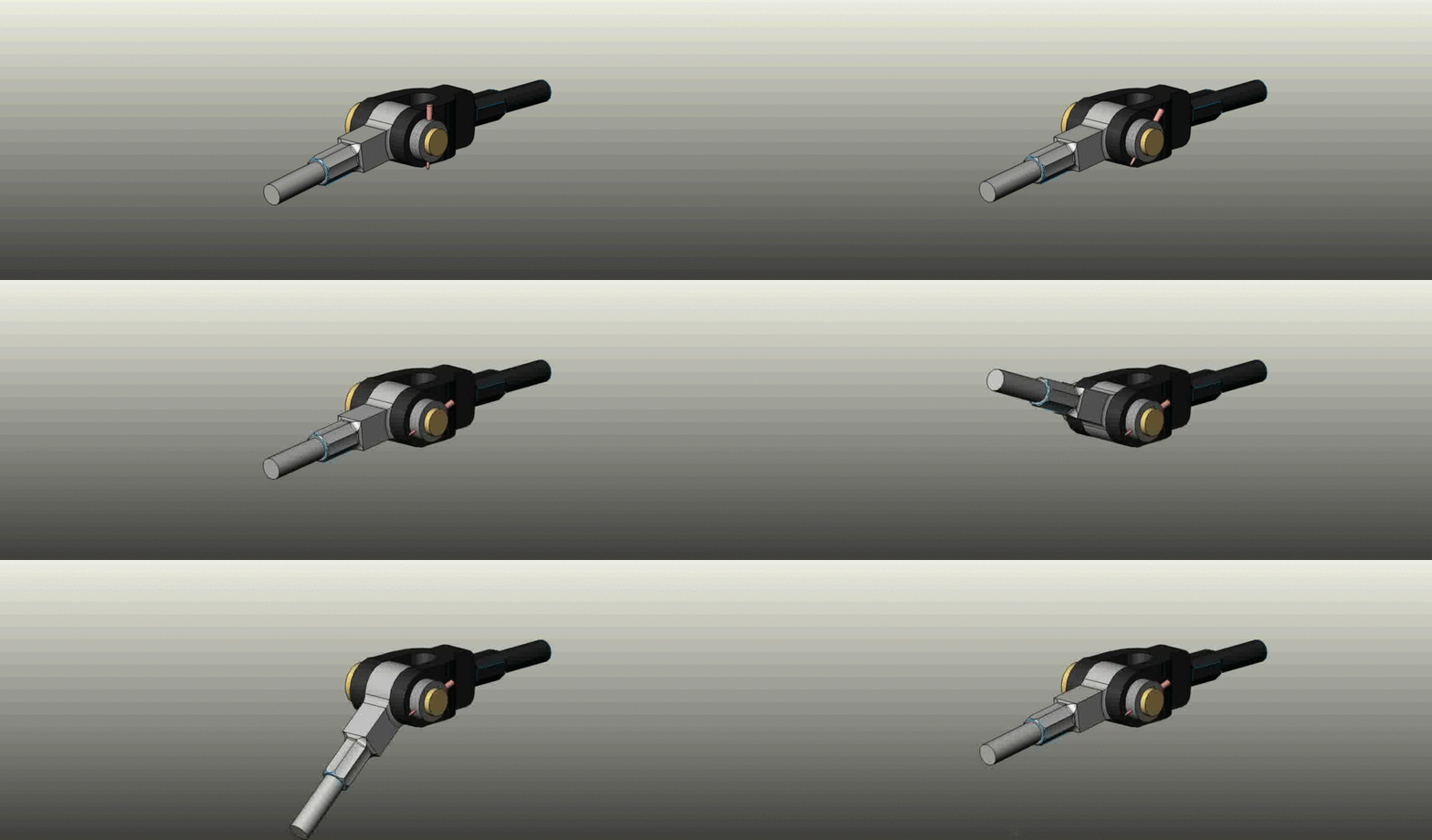
Fig. 2.2 Pin joint in action#

Fig. 2.3 Pin joint overview#
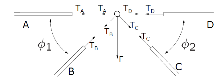
A joint, when isolated from it’s environment, has to be in equilibrium. The forces on the joint can be computed from the forces in the members connected to the joint and applying Newton’s third law, i.e. action is reaction. Equilibrium of the joint, means that the sum of all forces on the joint is zero. Applying this procedure to all joints, including the ones where the structure is supported, is called the method of joints. The unknown forces in the structure are the (normal) forces in the members and the reaction forces at the supports. A structure is called statically determinate if all the unknown forces can be determined by equilibrium only. In this case, it means that the method of joints should be able to solve all the unknown forces in a statically determinate truss structure. In Fig. 2.4 below we can see how the Method of Joints should be applied. Here we apply the method to all joints. Also in the support nodes having reaction forces. Optionally apply global equilibrium to the structure.
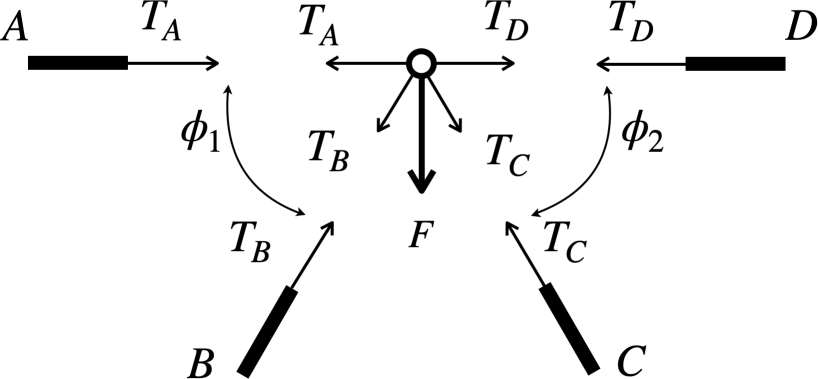
Fig. 2.4 Method of joints#
For the system above in Fig. 2.4 we can write the system of equations
When these types of systems are statically determinate they can be analytically solved. In Example 2.1 a simple application of this kind of system is shown.
Method of joints
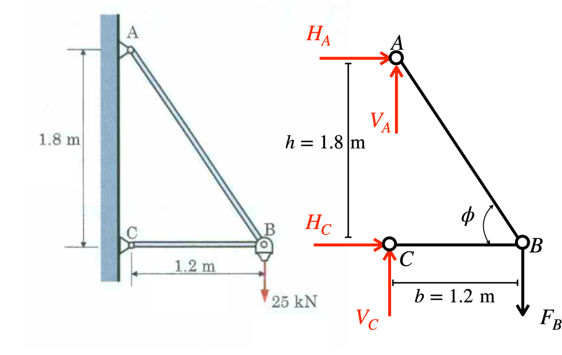
Fig. 2.5 Method of joints truss example#
For this example in Fig. 2.5a simple truss structure is given where forces are present on points \(A\),\(B\) and \(C\). We define the angle \(\angle CBA\) as \(\phi\). The distance between points \(C\) and \(A\) is \(h\) and between \(C\) and \(B\) we call \(b\). The point \(B\) feels a certain force \(F_B\) where \(A\) and \(C\) feel reaction forces which are given as \(H_A\), \(V_A\), \(H_C\) and \(V_C\). Next to this it is given that
Please find the force in all members and the reaction at the fixed supports at \(A\) and \(C\).
Solution
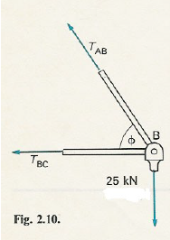
The first step is to define the tensile compontents \(T_{AB}\) and \(T_{BC}\) at the point \(B\). This is shown in Fig. 2.6.
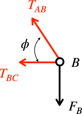
Fig. 2.6 Tension at \(B\)#
With this we can now set up the horizontal and vertical force balances in \(B\), given by
Where we can now cumpute the “tension” and the “compression” terms
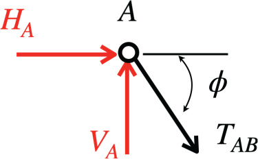
Fig. 2.7 Tension at \(A\)#
The next step is to now go to point \(A\) (Fig. 2.7) and compute the reaction forces \(H_A\) and \(V_A\) by the horizontal and vertical force balances with tenion components of \(T_{AB}\) given by
The reaction forces are now found to be
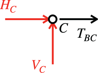
Fig. 2.8 Tension at \(C\)#
Finally in Fig. 2.8 point \(C\) the reaction forces can be found with similar procedures as done in \(A\) where
with as a last result
As a final check we can combine all the horizontal, vertical and moment elements which can be summed seperately and should give no net forces for a global equilibrium.
The horizontal components
give an equilibrium with the vertical compontens
doing the same. The equilibrium of moments holds with
and thus a global equilibrium is found showing that indeed the system is not in motion as expected.
Global equilibrium
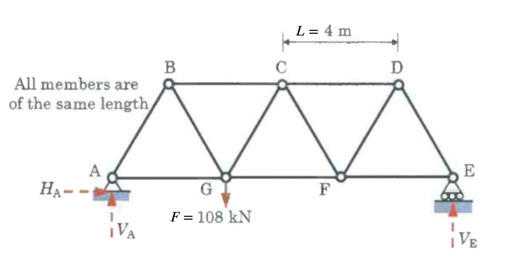
Fig. 2.9 Multi component truss structure#
The system in Fig. 2.9 above is a statically determinate, planar truss. It is described by a network of pin-connected members forming joints (labeled \(A\), \(B\), \(C\), etc.). The external load \(F\) is applied to the structure. Establish the overall balance of forces and moments to find the support reaction forces. Examinie each joint individually to compute the internal forces in the connecting members. The length between joints \(C\) and \(D\) (and similar) is defined as \(L\).
Some give numeical values are
Solution
The first step to find the reaction forces on the system is to concider the global equilibrium. Here the moment of the system also needs to be concidered. We thus find
which gives us the necessary relations to find that \(\displaystyle \implies {\color{red}V_E} = \frac{F}{3} \) and thus \(\displaystyle \implies {\color{red}V_A} = - V_E + F = -\frac{F}{3}+F=\frac{2}{3}F\).
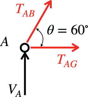
Fig. 2.10 Equilibrium of joint \(A\)#
Similar as to in Example 2.1 the force balances in each relevant joint are set up. We start with joint \(A\) which is depicted in Fig. 2.10. That the angle \(\theta\) at \(\angle GAB\) is found to be \(60^\circ\) just comes from the triangle between joints being equilateral.
We find the force balanes
With this the tensire forces can now be calculated by
Fig. 2.11 Equilibrium of joint \(B\)#
Now the same procedure for \(B\) as depited in Fig. 2.11 gives
for the force balances for the horizontal and vertical components in \(B\) with
as the tensile forces. Below in Fig. 2.12 The last type of free body diagram is shown. It is important that the force \(F\) also is included when setting up the force balances.
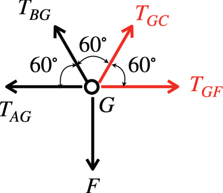
Fig. 2.12 Equilibrium of joint \(G\)#
With all these types of cases concidred with similar procedures all tensile forces can be computed.
Consider a 2D truss having \(N_\text{j}\) joints, \(N_\text{m}\) members and \(N_\text{r}\) unknown reaction forces. Assume we use a fixed Cartesian co-ordinate system \((x,y)\). At a joint \(i\), with \(1\leq i\leq N_\text{j}\), we have external forces \(F_x^{(i)}\) and \(F_y^{(i)}\) and/or reaction forces \(R_x^{(i)}\) and \(R_y^{(i)}\) (only at joints with support). The axial tensile forces in the members are denoted by \(T_m\), \(1\leq m\leq N_\text{m}\) and the angle of member \(m\) with respect to the positive \(x\)-axis is denoted by \(\theta_\text{m}\). For each joint \(i\) we have two equilibrium equations
where the sum is over the members \(m\) that are connected to joint \(i\). Note, that the left-hand side contains the unknown and the right-hand side the known forces. Apparently, we have \(2N_\text{j}\) equations for \(N_\text{m}+N_\text{r}\) unknown forces. For equilibrium to be sufficient for determining the forces in a truss (statically determinate) the number of equilibrium equations must be equal to the unknown forces, thus:
A truss is statically determinate if: \(N_\text{m} + N_\text{r} = 2N_\text{j}\)
A truss is statically indeterminate if: \(N_\text{m} + N_\text{r} > 2N_\text{j}\)
A truss is a mechanism if: \(N_\text{m} + N_\text{r} < 2N_\text{j}\)
Note
In order for the truss to be statically determinate, \(N_\text{m} + N_\text{r} = 2N_\text{j}\) must be valid for parts of the structure as well. In practice it means that the members are evenly distributed over the structure.
For statically determinate trusses the member forces and reaction forces can often be computed by determining the reaction forces from the global equilibrium of the structure first and then applying equilibrium of joints or equilibrium of whole sections of the structure. The latter procedure is called the method of sections, which can also be applied if only one or two member forces are needed for checking other (numerical) solution methods.
In the analysis of a truss it is advisable to quickly find the members that have zero force. These members are called zero-force members. Although zero-force members do not `carry the load’, they can increase the stability of the structure by supporting other members that would otherwise buckle due to compressive forces. These members usually have a smaller cross-sectional area than the members carrying load. Also, the structure could be designed for multiple load cases and that for the current load the member force is zero and for the other load cases it is not. Finding the zero-force members requires some training. For a 2D truss we can say that for a joint having no external or reaction forces and
there are two non-aligned members attached to the joint, both are zero-force members, or
there are three members attached to the joint, of which two are aligned, the third one is a zero-force member.
Method of Sections
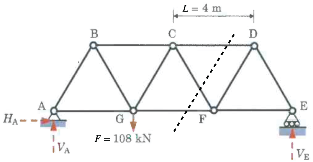
Fig. 2.13 Method of sections visualised#
When the same case as in Example 2.2 is concidered but only \(T_{CD}\) is asked, what is the most efficient way to go about this? A method that takes less time is the method of sections, an isolated part of the structure is in equilibrium as long as we account for the forces at the sections created.
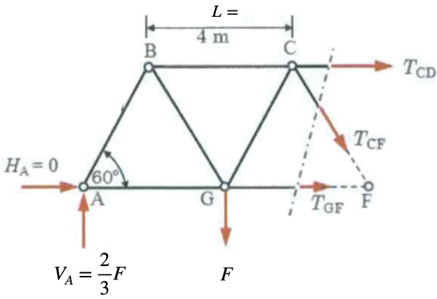
Fig. 2.14 Subsection of initial problem#
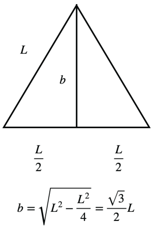
Fig. 2.15 Method of finding \(b\)#
The above Fig. 2.14 and Fig. 2.15 illustrate how
states the sum of moments \(\displaystyle \Sigma M_F= 0\). With the relation for \(b\) given in Fig. 2.15 the tensile force \(T_{CD}\) is related as
2.1.1. Analysis of 3D trusses#
In 3D there are three equilibrium equations for each joint and then we have the rule \(N_\text{m} + N_\text{r} = 3N_\text{j}\) for a statically determinate truss. The video below in Fig. 2.16 shows an example of how a 3D truss structure can look like.
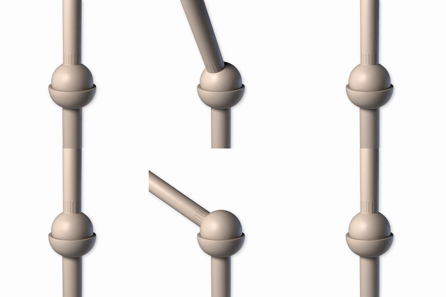
Fig. 2.16 Ball and socket joint in action#
2.2. Software for truss structures#
This section is not part of the exam. It is replaced by solving truss structures using the finite element package Marc/Mentat. There will be a separate training and your skill in using this package is tested in the intermediate and final tests during the quarter.
Although Marc/Mentat basically solves the equilibrium equations as derived using the method of joints, it doesn’t solve for the forces directly. The reason is, that it would only work for statically determined structures. In reality the forces are expressed in the displacements of the joints (called nodes in the finite element method). For that, the constitutive model for the material and strain-displacement relations (compatibility) are used. The equilibrium equations are solved for the displacement of the nodes, after first applying the correct support conditions for the displacements. This is called the displacement method. From the displacements other quantities such as the strains, stresses, member forces and reaction forces can be computed as a post-processing step. This works for both statically determinate and statically indeterminate structures.
2.3. Additional Video#
Below a video can be seen by The Efficient Engineer which explains trusses in an intuitive way. This is non mandatory material but just to give another perspective on the topic.