
7. Bending of beams: stresses#
Book: Sections 5.3 and 5.4 (excluding Subsections 5.3.2 and 5.3.4-5.3.7, but including Appendix B).
7.1. Normal stresses due to bending#
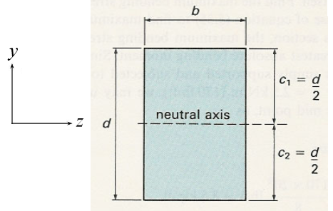
In this course, we only consider bending around the \(z\)-axis and cross-sections that are symmetric with respect to the \(y\)-axis in an orthogonal \((x,y,z)\) coordinate system having the \(x\)-axis along the axial direction of the beam (see Fig. 7.2 and Fig. 7.3). The displacement (bending) of the beam will only be in the \((x,y)\)-plane.
We start with pure bending, i.e. a state of (a piece of) the beam where the bending moment can be considered to be a constant. Since \(V=dM/dx\), the local shear force can be neglected and thus the deformation due to the shear force as well. In Fig. 7.1 a piece of a beam is shown under pure bending. The initially rectilinear line pattern is deformed, where the lines in axial direction become circular arcs having the same centre of curvature and the lines in cross-sectional direction remain straight and orthogonal to the circular arcs. This result can be verified experimentally.
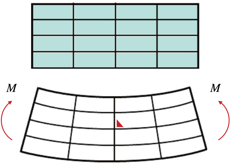
Fig. 7.1 Deformation of a beam in pure bending#
For a positive bending moment the axial lines on the upper side become shorter (negative strain) and the lower side become larger (positive strain). At some position in the beam the axial line will remain of the same length (zero strain). This line is positioned on the so-called neutral surface (see Fig. 7.2). The intersection of the neutral surface with the cross-section is called the neutral axis (see Fig. 7.3).
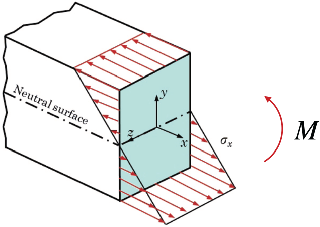
Fig. 7.2 Neutral surface#
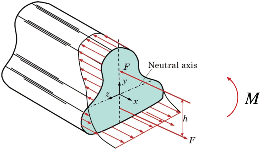
Fig. 7.3 Neutral axis#
7.2. Assumptions in the theory of beam bending#
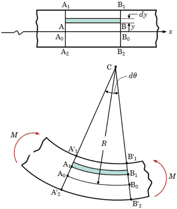
Fig. 7.4 Plane sections remain plane and normal; fibers form concentric arcs.#
Plane cross-section remain plane.
The longitudinal (axial) lines (in \(x\) direction) bend to circular arcs having the same center of curvature (see Fig. 7.4).
The stresses \(\sigma_y\) and \(\sigma_z\) in the \(y\)- and \(z\) directions are negligibly small compared to stress \(\sigma_x\).
De radius of curvature is large compared to the height dimensions of the beam, i.e. the curvature is small.
The material is linear elastic.
The Young’s modulus \(E\) is the same in tension and compression and independent from the position in the beam.
Definition 7.1
The position of the center of area (centroid) of the cross-section
Assuming a co-ordinate system \((x',y',z')\) having it’s origin in a point somewhere in the cross-section and the \(x'\)-axis in the direction of the beam’s axis, the position of the centroid in the cross-section is given by:
\(Q_{z'}\) and \(Q_{y'}\) are called the first moment of area of the cross-section with respect to the \(z'\)- and \(y'\)-axis, respectively. See also Section B.1 (appendix B).
We use a right-handed orthogonal \((x,y,z)\) co-ordinate system, where the \(x\)-axis is in the direction of the beam’s axis, the \(y\)-axis is the symmetry axis of the cross-section and the \(z\)-axis is on the neutral axis. The bending moment (vector) is orthogonal to the \((x,y)\)-plane, i.e. parallel to the \(z\)-axis. Using geometric arguments (see Figure 5.44b and page 249), the longitudinal (axial) strain is proportional to the distance to the neutral axis and the curvature (defined as \(1/R\)):
For the axial stress, we get:
Beam with rectangular cross-section
For a beam with rectangular cross-section a stress distribution is obtained as depicted in Fig. 7.2. For the axial force we get:
Using this, we find
or: the neutral axis passes through the centroid of the cross-section.
Definition 7.2
“The second moment of area \(I_{z'}\) with respect to the \(z'\)-axis”
The second moment of area with respect to the \(z'\)-axis is defined as:
Since we will mainly consider bending parallel to the \(z\)-axis, we will often denote \(I_{z'}\) by just \(I'\). Sometimes, \(I'\) is also called the “area moment of inertia”, because of the resemblance with the `moment of inertia’ used in the dynamics of rigid bodies. For bending parallel to the \(y'\)-axis, we similarly have the quantity \(I_{y'}\).
In addition to the \((x',y',z')\) co-ordinate system, we also introduce a translated \((x,y,z)\) co-ordinate system that has it’s origin in the centroid of area \((y'_\text{c}, z'_\text{c})\) of the cross-section. Then we can write for \(I'\):
From the definition of the centroid of area, we obtain: \(\displaystyle \int_{A}y'_\text{c} \,dA = 0\). Hence:
where \(I_\text{w.r.t. z-axis passing through the centroid}\) has been abbreviated to just \(I\). This is called the parallel axis theorem, also known as Steiner’s theorem.
Remark
the second moment of area is minimal for an axis passing through the centroid. See also appendix B.2 and the table in appendix B.5.
7.3. Additional Video#
This video by The Efficient Engineer provides a great introduction to the analysis of beams under load, explaining the fundamental concepts of Shear Force and Bending Moment diagrams. This video is non-mandatory and is purely to give a different perspective on the topic.