1. Simple tools#
Application of the work-energy principle
1.1. Introduction#
Before we take a look at advanced contemporary devices, we consider a number of simple instruments in this chapter. In everyday life we come across many simple instruments, whereby the incoming force (source force), often muscle strength of the human being, is increased or decreased and offered to a load process. Schlösser defines an instruments as follows: “Instrument is the name of a structure, which is used to carry out load processes with the help of mechanical energy sources.” Some examples of simple instruments are a nutcracker, a cork screw, a pallet truck, a car jack, a hammer or a hand drill (Fig. 1.1).
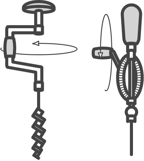
Fig. 1.1 Two alternatives for a manual drill.#
At first glance, it may not be clear, but all these devices are based on the same principle: the so-called work-energy principle. To understand the work-energy principle you need to know something about balance of forces, balance of torques and work. You have already worked extensively in secondary education with balance of forces and torques. Both are briefly repeated and summarized here. Thereafter the work-energy principle is introduced.
1.2. Balance of forces and torques (summary)#
If forces act on a body and it is at rest, or moves at a constant speed, there is a balance of forces. If we limit ourselves to two dimensions, then the following equations apply to the forces on that body:
Isaac Newton (1642-1727) [1]
Isaac Newton (1642-1727) was a British physicist, astronomer and mathematician, who is widely regarded as one of the most important scientists in history. Newton was a professor at Cambridge from 1667 till 1702, where he held the famous Lucasian chair in mathematics. Newton invented infinitesimal calculus to be able to express the laws of mechanics that now bear his name in mathematical form. He also gave a mathematical description of gravity, from which he could derive Kepler’s laws of planetary motion. In addition to his work on mechanics, Newton made key contributions to optics and invented the reflection telescope, which uses a mirror rather than a lens to gather light. Having retired from his position in Cambridge, Newton spent most of the second half of his life in London, as warden and later master of the Royal Mint, and president of the Royal Society.
Fig. 1.2 Portrait of Isaac Newton by Godfrey Kneller (1689).#
Here, \(\sum F_x\) in (1.1) is the sum of all forces in \(x\)-direction and \(\sum F_y\) in (1.2) is the sum of all forces in \(y\)-direction. Similarly, if a body does not experience rotational acceleration, there is an equilibrium of torques in any point \(A\) on (or even outside) the body. Point \(A\) therefore does not necessarily have to be the usually chosen pivot point.
For the torques on the body in relation to an arbitrary point \(A\) the following is valid:
In which \(\sum T_A\) represents the sum of all torques in relation to point \(A\). Torque is the rotational analogue of linear force and is also referred to as the moment of force (also abbreviated to moment). Torque is defined as the product of the magnitude of the perpendicular component of the force and the distance of the line of action of a force from the point around which it is being determined.
Tip
For applying force and torque equilibrium, it is essential to define a coordinate system and define the positive \(x\) and \(y\) direction and the positive direction of rotation therein.
Ladder against a wall
A ladder with length \(L\) of 10 meters and mass \(m\) of 30 kg stands against the wall and is at rest. It makes an angle of 60° with the ground, see Fig. 1.3 (a). There is a horizontal force from the wall on the ladder (normal force) and there is a vertical force (normal force) plus a horizontal force (friction) from the ground on the ladder. Assume that the center of gravity is positioned in the middle of the ladder. Calculate the magnitude of normal forces and the frictional forces.
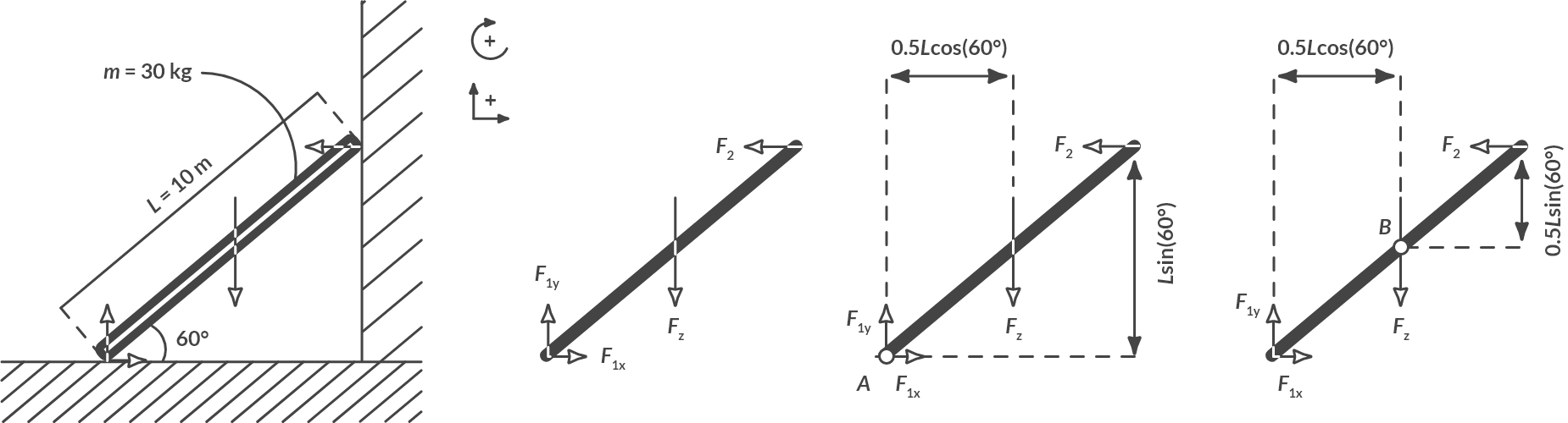
Fig. 1.3 Ladder against a wall.#
Solution
Fig. 1.3 (b) shows the forces on the ladder. We define forces to the right and up as positive. We furthermore define torques clockwise positively. The ladder is at rest, so there is balance of forces.
In these two equations there are three unknowns (\(F_{1x}\), \(F_{1y}\) and \(F_2\)). Three comparisons are needed to solve this system. The missing third equation follows from the torque equilibrium (the ladder does not turn) around an arbitrary point \(A\). When we choose point \(A\) on the ground, see Fig. 1.3(c), we get:
In combination with (1.5) this gives \(F_{1x} = F_2 = 85.0 \textrm{ N}\).
We can also use torque equilibrium around point \(B\) halfway up the ladder, see Fig. 1.3(d). We then get:
In combination with (1.5) this gives \(F_2 = F_{1x} = \frac{2.5 F_{1y}}{8.66} = 85.0 \textrm{N}\).
Choosing the pivot point is therefore not important when we consider the outcome. After all, there are always three comparisons with three unknowns.
Action is minus reaction / For every action, there is an equal opposite reaction
When two bodies exert a force on each other, forces always occur in pairs. We do not always experience that. When you sit in a chair you exert a force on the chair, but the chair also exerts a force on you. That force (normal force) is in balance with your gravity. This interaction is formulated in Newton’s third law. It states: “for equilibrium conditions it applies that for every force exerted on a body, that body reacts with an equally large but opposite force”.
If several bodies play a role in a balance of forces or moment, draw all bodies separately and only draw the forces that act on that specific body. This is called a free body diagram (FBD).
Nutcracker
A nutcracker increases the force that you exert through a lever mechanism. A small source force is then sufficient to crack a nut. Below you can see such a nutcracker. This nutcracker consists of three bodies: the lower body, the upper body and the axis at the pivot point.
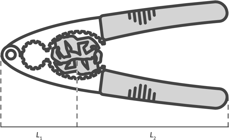
Fig. 1.4 Nutcracker.#
Draw all forces that act on the lower and upper arm, on the axis in the pivot point and on the nut.
Solution
We isolate the bodies and draw the forces that work on each body. Because the whole is in balance, balance of forces in the x and y directions and balance of torques must apply to every body. Note the notation of the arrows and the difference with pre-university education!
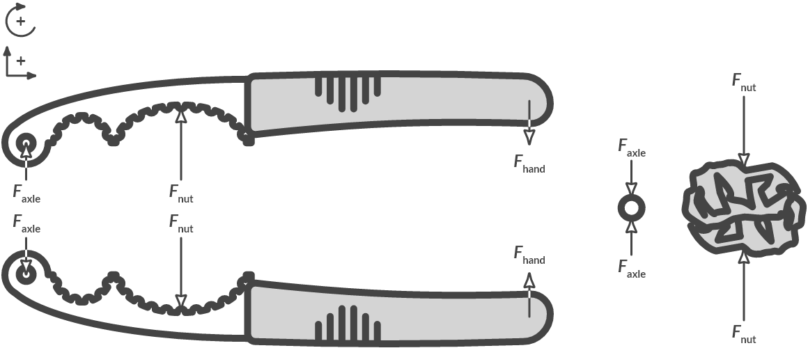
Fig. 1.5 Free body diagram of the nutcracker.#
Note
Note that application points and forces may also be indicated differently than at high school!
Calculate the magnitude of the axle load \(F_{\text{axle}}\) in relation to the force \(F_{\text{hand}}\) you apply with your hand, when \(L_1 = 35 \textrm{ mm}\) and \(L_2 = 105 \textrm{ mm}\).
Solution
From balance of forces on the upper arm follows:
From balance of torques around the pivot point follows:
With the equilibrium of forces from (1.11) it follows for \(F_{\text{axle}}\):
The axle load is 3 times greater than the force that you exert by hand.
Do you know the answer to the following question?
One-propeller drone
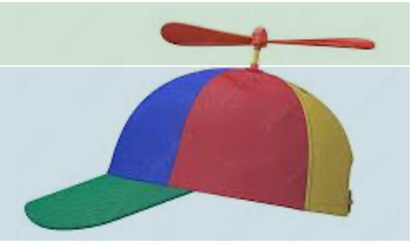
Fig. 1.6 Simple “drone” with one propeller.#
In this example we consider a one-propeller drone that is hovering in mid air. One of these types of drones can be seen in Fig. 1.6 It feels the gravity force \(F_z\) that is pulling it down (in negative z direction), and propeller(s) are used to generate lifting force \(F_{\textrm{prop}}\) to keep the drone in the air. This force is generated by rotating a propellor by applying a torque \(T_{\textrm{prop}}\) to it.
To keep the exercise simple, we will only consider the z-translational direction and the \(R_z\)-rotational direction. The other two translational and rotational degrees of freedom can be ignored.
The goal is to keep the drone hovering at rest.
What does this mean for the desired total force (= sum of all forces) and total torque (= sum of all torques) on the drone?
Derive the expressions for the sum of all forces and for all torques for the one-propeller drone. What can you conclude about the hovering capability of this drone?
Background information
This propeller exericises is inspired by the two videos below.
Solution
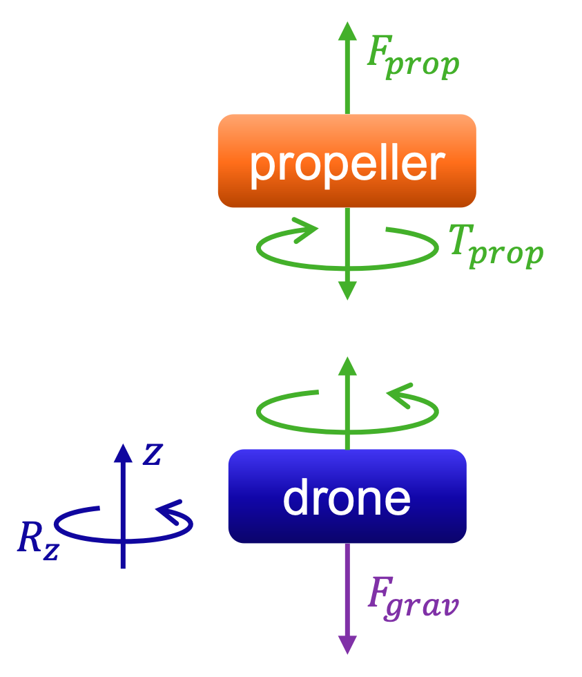
Fig. 1.7 Schematic of Forces and Torque on the drone and its propeller.#
The Force and Torque on the drone and propeller may be seen in Fig. 1.7. Hovering at rest implies that the total force and torque acting on the drone equals \(0\,\)N and \(0\,\)Nm.
The total sum of forces on the drone is zero, where the \(F_{\textrm{prop}}\) force is opposite and equal in magnitude as \(F_{\textrm{grav}}\). This is given by
\[-F_{\textrm{grav}} + F_{\textrm{prop}} = 0 \quad \Rightarrow \quad F_{\textrm{grav}} = F_{\textrm{prop}}. \]The sum of torques on the drone is zero. This is the case since for the drone to hover at rest, no net rotational motion is allowed, thus we have
\[ -T_{\textrm{prop}} = 0 \quad \Rightarrow \quad T_{\textrm{prop}} = 0. \]To hover at rest, no propeller torque is allowed. This corresponds to a propeller not rotating \(\Rightarrow\) the drone will either drop from the sky, will start spinning at a fixed height, or a combination of both.
1.3. Work and the work-energy principle#
1.3.1. Work of a force#
Consider an object moving a distance \(\Delta x\) meters. During that movement a constant force F acts on the object.
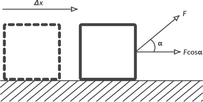
Fig. 1.8 A constant force \(F\) which works over an angle \(\alpha\), moves an object distance \(x\).#
If the force F and the displacement \(\Delta x\) make an angle \(\alpha\), then the force F has performed a work \(W\) for a displacement \(\Delta x\) of the magnitude of:
The force acting on an object does need not be constant. In that case we need to integrate the force \(F\) to obtain work \(W\):
1.3.2. Work of torque#
Consider an object performing a rotation over an angle of radians while applying a constant torque T to it. If the angular rotation and the torque have the same direction of rotation, then the torque has done work with a magnitude of:
This can be deduced by considering the moment as a force that moves over a curve (see Fig. 1.9).
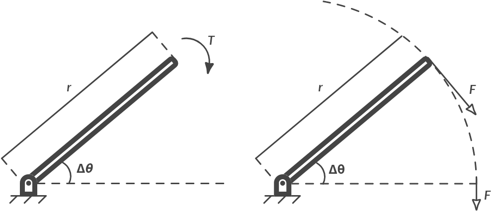
Fig. 1.9 (a) Torque and angular rotation, (b) force moving over a curve.#
The force F travels a path the size of the arc of the circle \(\Delta \theta \cdot r\). For the work that the force performs applies:
1.3.3. Work-energy principle#
When the work-energy principle is used, a machine is considered a black box with incoming work and outgoing work.
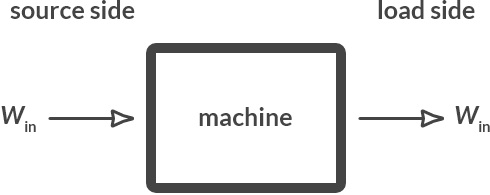
Fig. 1.10 Black box approach with incoming and outgoing work.#
The work-energy principle states that for an ideal loss-free machine the incoming work is the same as the outgoing work. With an ideal loss-free machine, no work is lost due to friction losses, slippery surfaces or the deformation of parts (for example, the stretching of cables).
We call the input force for a machine or instrument, or the force that is offered to the machine, the source force. We call the outgoing force of the machine, or the force consumed by the environment of the machine, the load force. It follows from the work-energy principle:
Therefore, by reducing the path that the load travels relative to the path that the source travels, a force can be increased. The latter ratio (between the distance covered by the load and the effort) is also referred to as the transmission ratio \(i\).
Ball on inclined plane
Explain how the work-energy principle applies to the lifting of a mass against an inclined surface.
Solution
By pushing a ball upwards against an inclining surface (pushing), instead of straight up, you do not have to deliver as much force, but you do have to travel a longer way. This is illustrated in Fig. 1.11.
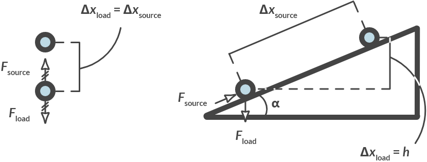
Fig. 1.11 (a) Push the ball vertically upwards, (b) push the ball against an inclined plane.#
Give an expression for the gear ratio \(i\) as a function of the inclination of the plane by angle \(\alpha\).
Solution
If you move a mass at an angle \(\alpha\), the following transfer ratio applies:
The following applies to the ratio between the source force and the load force:
Pulley
Explain how a double pulley uses the work-energy principle.
Solution
With a double pulley, the load force travels half the distance of the source force. As a result, the source force only needs to be half the load force. This is illustrated in Fig. 1.12. If the load \(\Delta x_{\text{load}}\) rises, both cords \(\Delta x_{\text{load}}\) in the loose pulley must shift. That is why \(\Delta x_{\text{source}} = 2 \Delta x_{\text{load}}\)
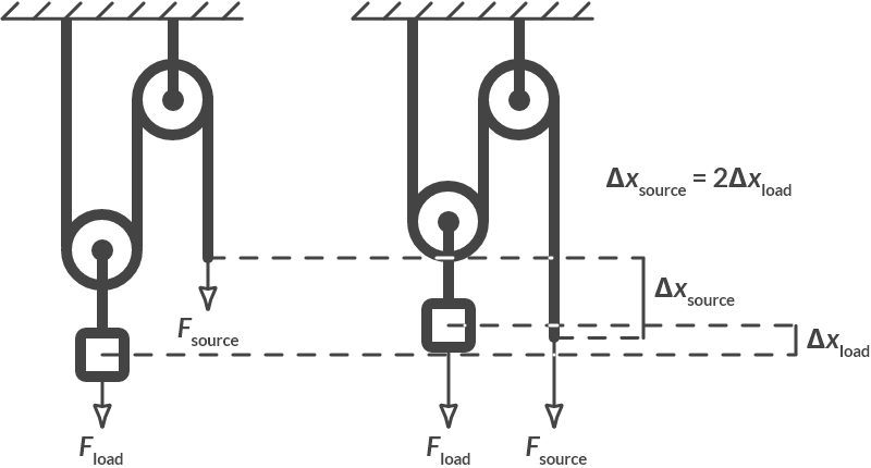
Fig. 1.12 Double pulley.#
Determine the transfer ratio.
Solution
The transfer ration is equal to: \(i = \dfrac{\Delta x_{{load}}}{\Delta x_{\text{source}}} = \dfrac{1}{2}\)
Gear transmission
Below you can see a transmission made with LEGO®. The driving shaft is attached to a gear with 24 teeth, which transfers the movement to a gear with 40 teeth.
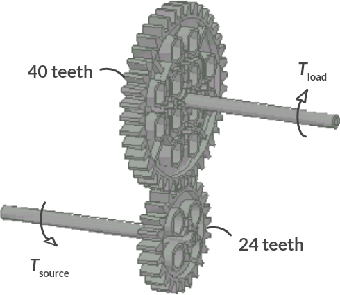
Fig. 1.13 Gear transmission.#
What is the ratio between the angular rotation of both gears? What is the transfer ratio?
Solution
If the gear on the source axis has turned once, the second gear has turned 24/40th. The transfer ratio is as follows:
What is the relationship between the torque the source delivers, and the load consumes? Is the source power strengthened or weakened here?
Solution
The ratio between source and load torques is therefore: \(T_{\text{load}} = \dfrac{T_{\text{source}}}{i} = \frac{40}{24} T_{\text{source}}\). This transmission thus increases the source force.
Gear transmission (2)
Below you can see a more complex transfer made with LEGO®. Calculate the transfer ratio between input (source) and output (load) axis.
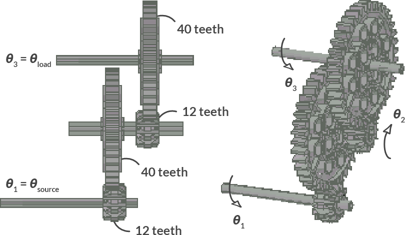
Fig. 1.14 Gear transmission (2).#
Solution
The following applies to the angular rotation of the different axes:
The outgoing angle rotation is 0.09 times as small. The outgoing torque is therefore 1/0.09 = 11.1 times as large. Also note that the direction of rotation of the axes 1 and 3 is the same.
Car jack
Fig. 1.15 shows a car jack that typically lies in the trunk of many cars. By an arm connected to a spindle, the structure ‘unfolds’. The transfer ratio can easily be determined experimentally. A student has carried out such an experiment for the car jack in a Peugeot 205. He observes that if the arm (\(r\) = 50 cm) has been round 20 times, the car is raised 25 cm.
What is the transfer ratio?
Solution
The transfer ratio is the ratio between the displacement of the load and the source:
If you can deliver a maximum force of 100 N, which mass can you jack up?
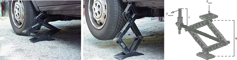
Fig. 1.15 Car jack.#
Solution
The source power is therefore increased by a factor of \(1/0.00398 \approx 251\). If you can deliver a maximum of 100 N, you can therefore lift cars up to approximately \(251 \cdot 100/9.81 = 2500 \textrm{ kg}\)!
Note
The question is of course whether the jack does not collapse under that load …
1.3.4. Power of a force and a torque#
The power of a force is equal to the work that the force performs per unit of time:
If the force is constant over time, then we get after differentiation (product-rule):
If a constant force \(F\) is exerted on an object, and the object moves at a constant speed \(v\), the force \(F\) supplies a power \(P = F \cdot v\).
For a torque the power can be derived in the same way. If a constant torque \(T\) acts on an object and the object rotates at a constant angular velocity , the moment produces a power:
Car jack (2)
We look again at the car jack of Example 7. We lift a delivery van of 4000 kg in 20 seconds, with constant speed and power, over a distance of 50 mm. Assume that the force is evenly distributed between the jack and the remaining three wheels.
What is the power of the load force?
Solution
- (1.27)#\[ P_{\text{load}} = F_{\text{load}} V_{\text{load}} = 1000 \cdot 9.81 \cdot \frac{0.05 \textrm{m}}{20 \textrm{s}} = 24.53 \textrm{ W} \]
At what angular speed \(\omega\) do you have to turn the arm of the jack?
Solution
The transfer ratio is known from the previous car jack example, \(i\) = 0.00398. To raise the car by 50 mm, the source force on the arm has therefore traveled \(x_{\text{source}} = 0.050/i = 12.56 \textrm{m}\) (!). In other words, \(12.56/2 \pi r = 4\) revolutions in 20 seconds, or \(0.2\) revolution per second. The angular speed is:
Which torque must be delivered to the jack?
Solution
We derive the source force from the transmission ratio:
The arm of the jack is 0.5 meters, so the moment that is delivered is:
What is the capacity that the “lifter” must offer? What stands out?
Solution
- (1.31)#\[ P_{\text{source}} = T_{\text{source}} \cdot \omega_{\text{source}} = 19.5 \textrm{ [Nm]}\ \cdot \frac{2}{5}\cdot \pi\textrm{ [rad/s]} = 24.5 \textrm{ W} \]
The power of the source force is equal to the capacity of the load force. This is entirely according to the work-energy principle. According to the work-energy principle, the outgoing work is the same as the incoming work. Per unit of time (per second), the work-energy principle still applies. It then states: the outgoing power equals the incoming power. This only applies to loss-free machines!
1.4. What lies ahead#
Balance of forces and torques are part of the basic knowledge of a mechanical engineer and return in all sorts of subjects and assignments. Drawing up and resolving balance of forces and torques, for example, plays an important role in determining the load on machine parts. In the next chapter you will become acquainted with mechanics and construction theory. This discipline investigates whether a machine (component) can bear a certain load or whether the material collapses.
In combination with work and power, forces and torques also play an important role in drive train technology. In the drive train technology, a suitable source process (for example a motor) is searched for with a given load process (for example moving a mass). That usually does not work; the source characteristic and the load characteristic do not have a common operating point. That is why source and load are usually linked to a transmission. Here we have assumed loss-free machines. In reality, no machine is loss-free, but subject to for instance deformation and friction. The discipline of mechanics is concerned with the deformation of machine (parts) under a certain load. The discipline drive train technology and tribology focus on drives, losses due to friction and on methods to reduce friction losses.
The principle of smart work is reflected in many disciplines of mechanical engineering. If you pay attention, you will come across many examples in daily life. By making an estimate of the path that the source force travels and the path that the load force travels, you can easily estimate how much the incoming force will be strengthened. As an indication, you should check what the gear ratio on your bike is in the different gears.
1.5. Problems#
For the following exercises use symbols as long as possible and only in the end fill in the values given.
Exercise 1.1 (Pallet Jack)
Using a pallet jack we want to lift a pallet of apples (mass \(m\) = 1000 kg) from the ground. In Fig. 1.16 you schematically see one pumping movement. The lever is pulled down and without applying any force the lever returns to its original position, which is vertical. After a total of 5 pumping movements the pallet is displaced 3 cm in height.
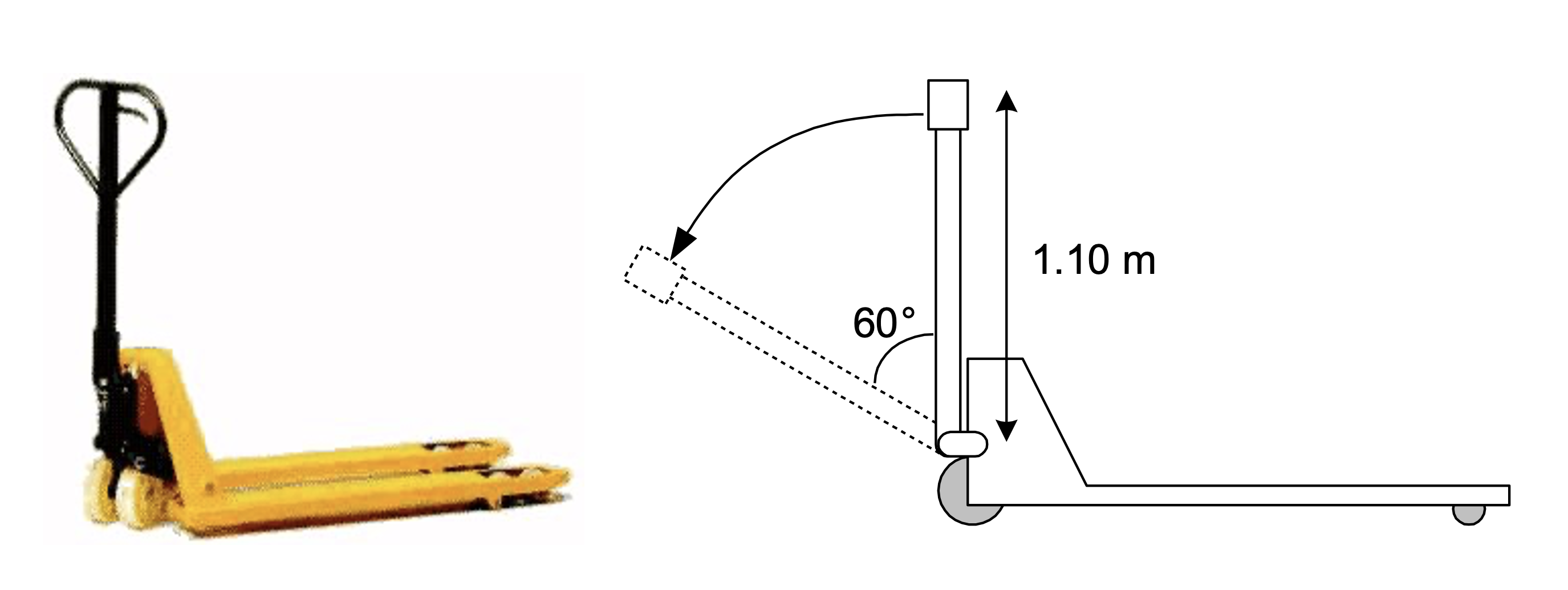
Fig. 1.16 Pallet jack (left), Pumping movement (right).#
Determine the ratio of the displacement of the source force (force on the pumping handle) versus that of the load force (apples).
Tip
Pay attention to the definition of the “transmission ratio” as explained in the theory, see section Section 1.3.3.
Is the source force amplified or reduced and by which factor?
Compute the force the person has to apply to lift the apples.
Compute the work the person has to deliver to raise the pallet of apples by 3 cm. You can get the answer by using two different approaches. Do both of them.
Exercise 1.2 (Two-propeller drone)
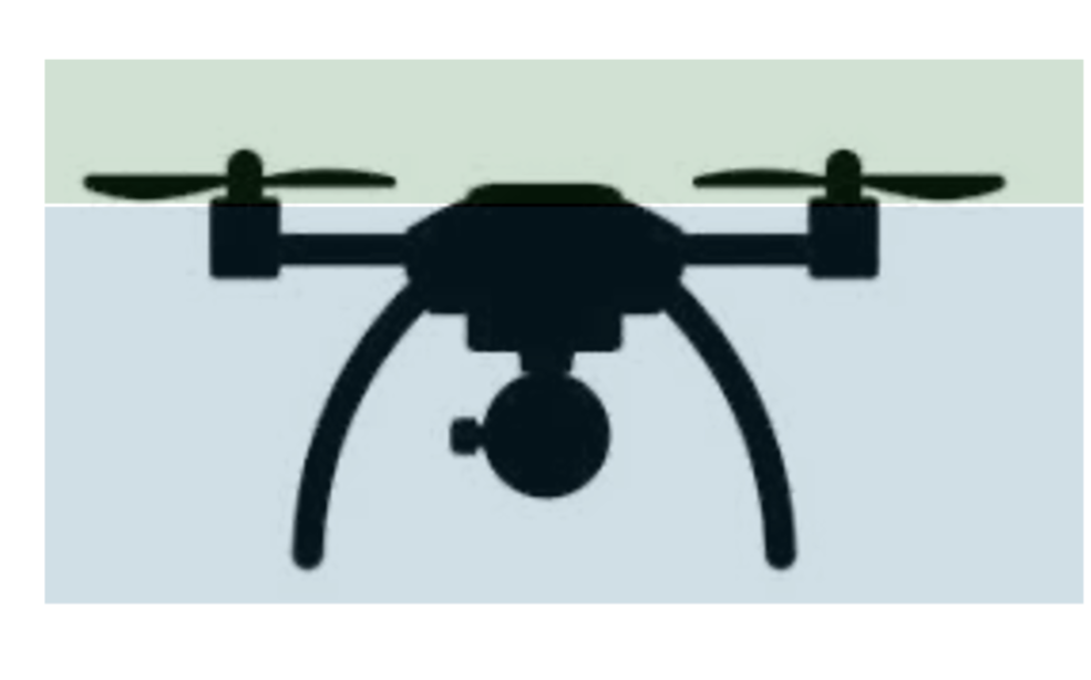
Fig. 1.17 Image of a two propellor drone.#
For the stability of the drone, in practice more than one propeller is used. Similar to Example 3 but let us now consider a drone with two propelling blades, where we will only consider the \(z\)-translational direction and the \(R_z\)-rotational direction. The other two translational and rotational degrees of freedom can again be ignored.
Sketch a free-body diagram of the drone and its two propellors and define the forces and torques acting on the bodies, and indicate their direction.
Derive the expressions for the sum of all forces and for all torques for the two-propeller drone. How can you interpret the solution for the propeller torques? Would this drone function as desired?
We intend to use this two-propeller drone for surveillance purposes. For simplicity, the body of the drone can be assumed to be rectangular, with lateral dimensions of \(30\,\)cm, and a thickness of \(50\,\)mm. The body is manufactured from a polymer composite material, with a density of \(2000\,\)kg/m3. The weight of camera is allowed to vary between \(50\) and \(150\) grams. The weight of the motors may be neglected.
Calculate the force that each of the two propellers of this drone need to overcome in order to hover in position during a surveillance assignment.
How would the above-derived force balance when the drone is vertically ascending at constant velocity?
Exercise 1.3 (Four-propeller drone)
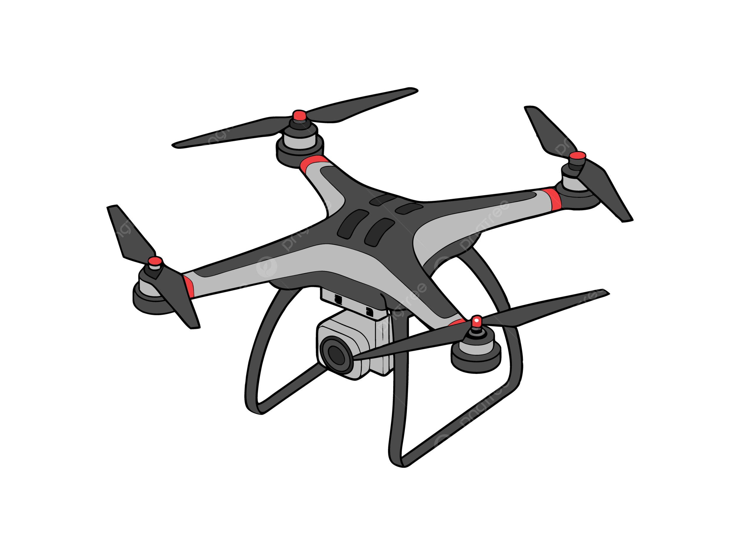
Fig. 1.18 Image of a four propellor drone#
Now for the grand finale a whopping four propeller drone is propelled. An image of this type of drone and its schematic may be found in Fig. 1.18 and Fig. 1.19.
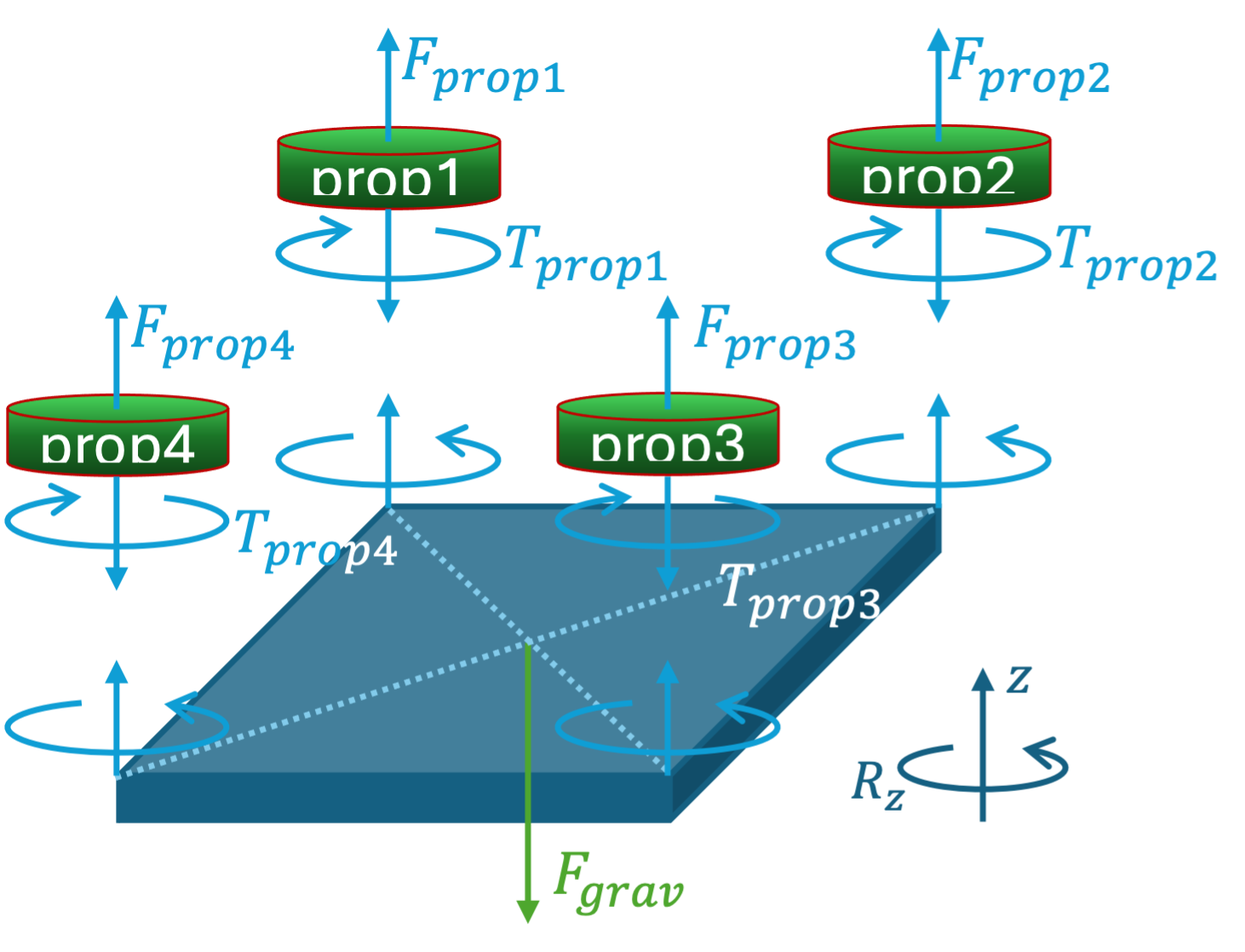
Fig. 1.19 Schematic of Forces and Torque on the drone and its propeller.#
Derive the expressions for the sum of all forces and for all torques for the four-propeller drone. Can this drone hover at rest?
Assume that propellers 1 and 2 are rotating in opposite direction from propellers 3 and 4, i.e., \(\displaystyle T_{\textrm{prop1}}=T_{\textrm{prop2}}=-T_{\textrm{prop3}}=-T_{\textrm{prop4}}.\)
Check that the sum of torques is indeed \(0\,\)Nm. What does this mean for the spinning of the drone in \(R_z\)-direction?
In practice, the torque of a propeller is proportional to the force that it can generate. In other words, the faster the propeller spins (due to a higher torque), the larger the lifting force of the propeller. \(\displaystyle T_{\textrm{prop}} = \alpha \cdot F_{\textrm{prop}}\) with \(\alpha>0\). Use this information to
Find an expression for \( \displaystyle F_{\textrm{prop1}} + F_{\textrm{prop4}}\) as a function of \( \displaystyle F_{\textrm{prop2}} + F_{\textrm{prop3}}\) and \(\displaystyle F_{\textrm{grav}}.\)
Find the solution for \( \displaystyle F_{\textrm{prop2}}\) and \( \displaystyle F_{\textrm{prop4}}\) when \( \displaystyle F_{\textrm{prop1}} = F_{\textrm{prop3}} = F_{\textrm{grav}}/4.\)
Exercise 1.4 (Transmission of a bike)
A sport bike has two gear-wheels in the front (52 and 42 teeth) and 5 gear-wheels on the rear (12, 16, 20, 24, 28 teeth). The diameter of the rear wheel is 70 cm. The description above is illustrated in Fig. 1.20 below.

Fig. 1.20 Gear-wheel transmission of a sport bike.#
The pedal has a revolution speed of 60 rotations per minute. The revolution speed of the rear wheel depends on the chosen gear.
Calculate the rotational velocity \(\omega\) of the rear wheel (in rad/s) for both the largest ratio 52/12 and also for the smallest (42/28). Put the answers in a table as Table 1.1.
Tip
The radius of a gear-wheel scales proportionally with the circumference and hence the number of teeth \((P=2 \pi r)\).
\(\omega\) (rad/s) |
12 |
16 |
20 |
24 |
28 |
|---|---|---|---|---|---|
52 |
|||||
42 |
The force on the pedal is 100 N. Calculate the force on the road. Do this for both cases “52/12” and “42/28”. Put the answer in a table as shown below.
Tip
Define a point A on top of the big gear-wheel and a point B on top of the small gear-wheel.
First calculate the force in the chain at point A and use that subsequently in point B. Put the answers in a table as Table 1.2.
\(F_{\text{road}}\) (N) |
12 |
16 |
20 |
24 |
28 |
|---|---|---|---|---|---|
52 |
|||||
42 |
Which gear-wheel combination would you use when you have to apply a lot of force, like when riding up a steep mountain?
And which gear-wheel combination would you use to maintain a high velocity?