4. Heat machines#
4.1. Introduction#
Flow machines transfer energy to a flowing medium or extract it using mechanical energy. Heat machines do the same, only heat is used now. This can be through the addition of heat (e.g. via combustion) or from the withdrawal of heat (e.g. a fridge) or from the transfer of heat (e.g. a heat pump). Our current energy supply is largely based on heat machines such as engines and gas turbines. Energy is getting scarce and more expensive. Existing fossil energy sources must be handled with the utmost care and, where possible, forms of renewable energy must be developed. In this chapter we deal with all processes in which thermal energy plays a role. Two main areas can be distinguished, namely energy storage and transport, and thermodynamics. Energy storage and transport play a particularly important role in the process industry, where substances must be cooled and heated. This is possible in large-scale installations, such as a waste incineration plant where the heat in flue gases is recovered via heat exchangers and is reused for heating houses or greenhouses.
Thermodynamics is used in the design of systems in which cyclic processes take place. Consider, for example, a refrigerator in which the cooling medium is pumped around and absorbs heat in the cooling space and releases heat in the rear radiator. Thermodynamics also plays a major role in drive train technology. Just think of the gasoline engine, the diesel engine, but also the aircraft engine and the rocket engine.
In this chapter you will become acquainted with some principles of heat storage and transport and with circuit processes in thermodynamics.
4.2. Storage of heat#
When we add or remove heat from an object, the heat content of that object changes.
If we assume that the object consists of a solid or a liquid, the following can happen:
A phase change occurs; the solid melts or the liquid evaporates. In either case, the temperature remains unchanged, or:
No phase transition occurs; the temperature of the object then increases or decreases.
In the latter case, the following applies to the temperature change:
In which:
\(\Delta Q\) is the added or removed heat in [J],
\(m\) is the mass of the object in [kg],
\(c\) is the specific heat capacity in [J kg\(^{-1}\) K\(^{-1}\)] or [J kg\(^{-1}\) C\(^{-1}\)] and
\(\Delta T\) is the temperature change in [K] or [°C]
Instead of using the specific heat capacity \(c\), the heat capacity \(C\) of an object is also often used. Especially if the object consists of different materials. The heat capacity of an object determines how much energy must be supplied for 1 degree temperature rise. In equation form:
The heat capacity of one kilogram of water is equal to: \(C_1\) kilogram water = \(m \cdot c_{\textrm{water}} = 1 \cdot 4180 = 4180\, \textrm{J/K}\)
Heat storage tank
We use heat storage tanks to store excess heat that we can use later. We approach the storage tanks as cylindrical (see Fig. 4.1). The following applies to the dimensions of the storage tanks: h = 5.0 m; R = 2.0 m and d = 3.0 cm. The storage tanks are made of aluminum. Furthermore, the following is given: \(c_{\textrm{aluminium}} = 880 \, \textrm{J/kgK}\), \(c_\textrm{water} = 4180 \, \textrm{J/kgK}\).
For safety reasons, the temperature of the vessel must remain between 20 °C and 55 °C. What is the maximum amount of heat that can be stored in the vessel? Disregard heat losses to the outside world or assume that the storage tank is perfectly insulated.
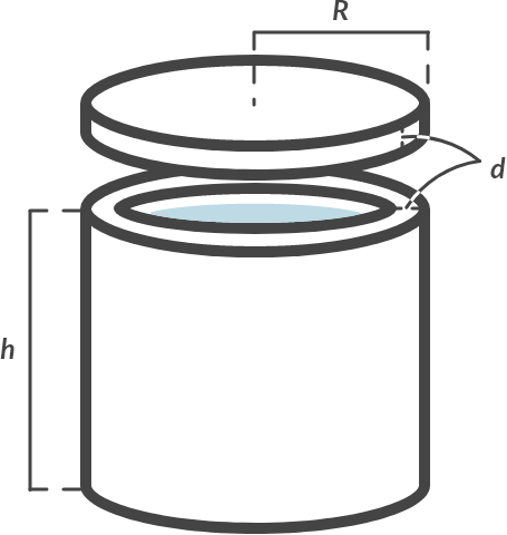
Fig. 4.1 (a) Heat storage tanks (b) schematic representation of the storage tank with dimensions.#
The heat capacity of the tanks is equal to the heat capacity of the water plus the heat capacity of the tank wall:
You can therefore store in a tank:
Note
The contribution of the aluminum tank to the total heat capacity is low, namely 2.5%.
This is on the one hand because the mass of the aluminum casing is much less than that of the water.
Moreover, the specific heat of that aluminum is also much less than that of the water.
4.3. Heat transfer#
There are three basic mechanisms on which heat can be transferred, namely conduction, flow (convection) and radiation.
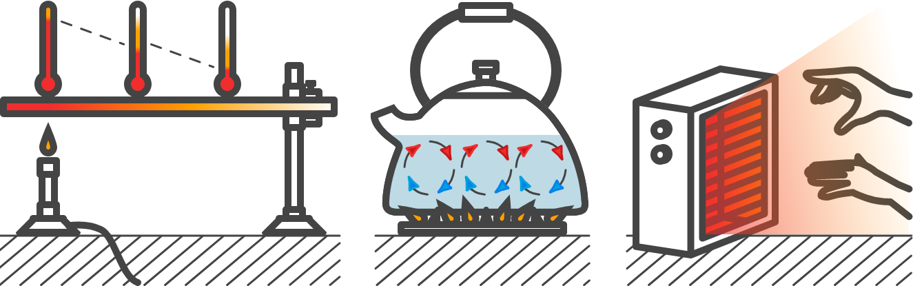
Fig. 4.2 (a) Conduction, (b) convection, (c) radiation.#
If you put a metal spoon in a pan filled with water, the whole spoon will become warm at some point. The heat is transported through the spoon through conduction. If you hold your hand next to the pan you will feel heat radiation. And if you keep your hand above the pan, you will feel heat flow through the rising vapors.
4.3.1. Heat flow by conduction#
If there is a temperature difference over a medium, the heat will flow from the area with the higher temperature to that with a lower temperature. In the context of this course, we only consider 1-dimensional heat flow, so only in the x direction, as displayed in Fig. 4.3
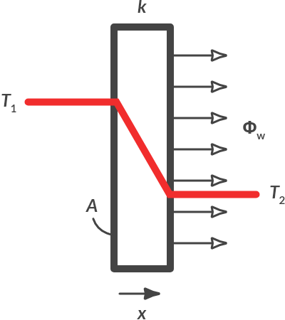
Fig. 4.3 Heat flow by conduction.#
The heat flow through a medium is mathematically described by Fourier’s law:
In which:
\(\phi_w\) is the heat flow in [W],
\(\frac{dT}{dx}\) is the temperature gradient in the medium [K/m] or in [°C/m],
\(A\) is the surface through which the heat flows in [m\(^2\)] and
\(k\) the material-dependent thermal conductivity coefficient in [W/mK].
Joseph Fourier (1768-1830) [1]
Jean-Baptiste Joseph Fourier (21 March 1768 – 16 May 1830) was a French mathematician and physicist born in Auxerre and best known for initiating the investigation of Fourier series, which eventually developed into Fourier analysis and harmonic analysis, and their applications to problems of heat transfer and vibrations. The Fourier transform and Fourier’s law of conduction are also named in his honour. Fourier is also generally credited with the discovery of the greenhouse effect.
Fig. 4.4 Portrait of Joseph Fourier.#
The minus sign indicates that the heat flow is directed from a high to a lower temperature. If the temperature decreases in the positive x direction, as is the case in Fig. 4.3, the temperature gradient dT/dx is negative and the heat flow (in the positive x direction) is positive.
The thermal conductivity coefficient \(k\) depends on the material. A good conductive material, such as silver or copper, has a high thermal conductivity. A poorly conductive (well-insulated) material, such as glass or air, has a low thermal conductivity. Below in Table 4.1 you can see several thermal conductivity coefficients \(k\) of common materials.
Material |
\(k\) [W/mK] |
|---|---|
Silver (pure) |
410 |
Copper (pure) |
385 |
Aluminum (pure) |
202 |
Nickel (pure) |
93 |
Iron (pure) |
73 |
Steel 1% C |
43 |
Lead (pure) |
35 |
Oak |
0.17 |
Windows glass |
0.78 |
Glass wool |
0.038 |
Water |
0.556 |
Air |
0.024 |
Carbon dioxide |
0.0146 |
Insulation heat storage tank
We look again at the heat storage tank of Example 1. In that example, we have neglected heat loss to the environment. Now assume that there is only heat loss due to conduction. The water in the storage tank has a temperature of 55 \(°C\). The outside temperature is \(20 °C\). We assume that the heat can flow through all wall parts of the storage tank and that the temperature of the water in the tank is homogeneous. How large is the heat loss? Which material would be better suited for insulation?
Solution
Over the wall of the storage tank there is a temperature difference of \(20 °C - 55 °C = -35 °C\). (Where the positive x direction is outwards.) The temperature decreases linearly, the gradient is:
Furthermore, it is known that the storage tank is made of aluminum, k = 202 W/mK. The surface through which the heat flows is:
Therefore, the heat flow from the storage vessel to the outside (the heat loss) is equal to:
In order to keep the contents of the vessel at \(55 °C\), a heating system must supply approximately 2070 kW of heat!
4.3.2. Heat transfer by radiation#
Objects that have heat will radiate this heat. This is done with electromagnetic waves. Until certain temperatures, these waves are not visible to the naked eye. With infrared cameras you can visualize that heat. Such cameras are used, among other things, in night vision equipment.
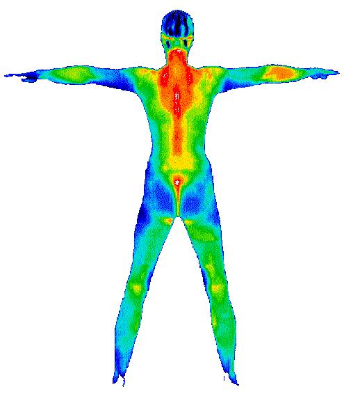
Fig. 4.5 Infrared image showing the temperature distribution of a human.#
If an object becomes warm enough, it will also emit visible light. Just think of glowing steel or the glowing spiral in a radiant stove or toaster.
The amount of emitted radiation can be calculated with:
In which:
\(\phi_w\) is the heat flow in [W],
\(A\) is the surface of the radiating object in [\(m^2\)],
\(\sigma_z\) a proportionality constant, always equal to \(56.7 \cdot 10^{-9} \quad [\textrm{W/m}^2 \textrm{K}^4]\) (=Stefan-Boltzmann’s constant)
\(T\) is the absolute temperature of the radiating object, so always in [K],
\(\epsilon\) is the absorption or emission factor of the surface, depending on the color and surface properties.
Material |
Emission factor \(\epsilon\) |
|---|---|
Coppwe oxide |
0.74 |
Aluminum oxide |
0.80 |
Paper |
0.90 |
Glass |
0.92 |
Wet ice |
0.95 |
Exactly the same relationship applies to the amount of radiation that a small object absorbs, with the difference that \(T\) is then the temperature of the environment. If the object (indicated by index 1) is small relative to the environment (index 2), the net heat transfer from the object to the environment can be described as:
In which \(A_1 \sigma_z \epsilon_1 T_1^4\) is the amount of radiation the object emits and \(A_1 \sigma_z \epsilon_1 T_2^4\) the amount of radiation the object absorbs.
Solar collector
In 2001 there were 15,000 households in the Netherlands that used solar collectors for obtaining hot water. The solar collectors collect solar radiation and give heat to water that flows under the collectors. Around noon on an average spring day, such a collector absorbs \(1000\textrm{W/m}^2\) of solar energy.
The solar collector has a temperature of \(60\) °C. Furthermore, it is stated that the emission factor \(\epsilon\) of the solar collector is 0.90 and that the area \(A\) of the solar collector is \(3.0 \textrm{ m}^2\). The outside temperature is \(30 °C\).
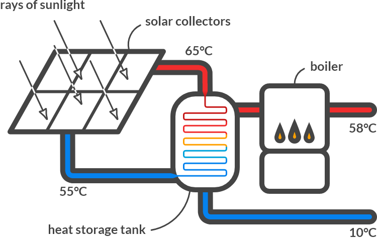
Fig. 4.6 (a) Solar collector (source: Navem), (b) Schematic representation of the solar water heater.#
Which forms of heat transfer play a role in the solar collector?
Solution
The solar collector is warmer than the environment. The solar collector absorbs heat by radiation from the sun. The collector loses heat to the environment through radiation and via conduction and convection to the colder (flowing) ambient air. The collector also releases heat via conduction and convection to the colder water that flows through the collector.
Calculate the amount of heat that the solar water heater loses via radiation to its environment? If we neglect other losses, how much heat is left to heat the water?
Solution
The collector (\(60 °C\)) emits heat through radiation, the size of:
The solar collector also absorbs heat from the environment (\(30\) °C) via radiation, the size of:
The collector absorbs \(\phi_{w,z} = AI = 3.0 [\textrm{m}^2] \cdot 1000\, \textrm{W/m}^2 = 3000 \cdot 10^3\, \textrm{W}\) from the rays of the sun.
The solar collector therefore has \(3000 - 1882 + 1290 = 2408\, \textrm{W}\) of net radiant heat to heat the water.
4.3.3. Heat flow by convection#
If a medium is stationary and there is a temperature difference over that layer, then there is conduction. Due to conduction, heat passes from the high to the low temperature. The temperature is linear over the medium, the temperature gradient is constant. This is shown in Fig. 4.3. If the medium flows at a certain speed, the temperature trend is different, see Fig. 4.7 We are talking about flow, or convection.
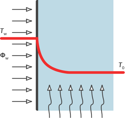
Fig. 4.7 Heat flow by convection in flowing air.#
With gaseous and liquid media (fluids), there is usually convection. If the flow is not imposed (by a pump or the wind, for example) spontaneous flow often arises due to the temperature difference. An example of this spontaneous flow is shown in Fig. 4.2(b). Initially, the water stopped in the kettle. Due to the temperature difference, the warmer water flows up and the colder water flows down.
Calculating convection is a lot more complicated than calculating conduction. The exact course of the temperature gradient is not considered. For the situation in Fig. 4.7, where a hot plate gives off heat to a flowing liquid or gaseous medium, the heat flow can be calculated with:
In which:
\(\phi_w\) is the heat flow in [W],
\(A\) is the surface through which the heat flows in [m\(^2\)],
\(h\) is the heat transfer coefficient [W/m\(^2\)K] and
\(T_w-T_0\) the temperature difference over the flowing medium [K] of [\(° \textrm{C}\)].
The heat transfer coefficient \(h\) depends on the medium, but also on the flow velocity of the medium, the direction of flow and the type of flow (turbulent or laminar). The values of \(h\) are determined by means of experiments. The value of \(h\) will be given per situation within the framework of this course.
Flowing air can dissipate more heat than stationary air.
What can you say about the relationship between \(h_{\text{air}}\) and \(k_{\text{air}}\) ?
4.4. Energy conversion, heat and efficiency#
Many processes are conceivable that add or remove heat to a system. In the previous section we looked at the basic mechanisms on which heat can be transported. In this section we consider the process and its return. We define the efficiency of a heating or cooling process as follows:
Hotplate
A pan with 2.0 liters of water is standing on a hotplate. At t = 0 the water has a temperature of \(20 °C\). The hotplate has an electrical capacity of 1000 W. The efficiency of the hotplate is 80%. The water must be heated from \(20 °C\) to \(70 °C\). How long is the warm-up time? Neglect the heat capacity of the pan. (Why is that allowed?)

Fig. 4.8 Hotplate heats pan with water.#
The amount of heat supplied to the water is per second:
The increase in temperature per second is equal to:
The warm-up time is then equal to: \(\Delta t_{\textrm{warm-up}} = \frac{70-20}{0.096} = 5.2 \cdot 10^2 \, \textrm{s}\)
Note
Note the difference between the symbols: \(t\) for time and \(T\) for temperature.
Heat exchanger
In a gas water heater water is heated by flames. The cold water flows through the tubes and is heated at the exit by the heat supplied from the flames. It is stated that the combustion yields 45 kW. The heat transfer efficiency on the flowing water is 75%.
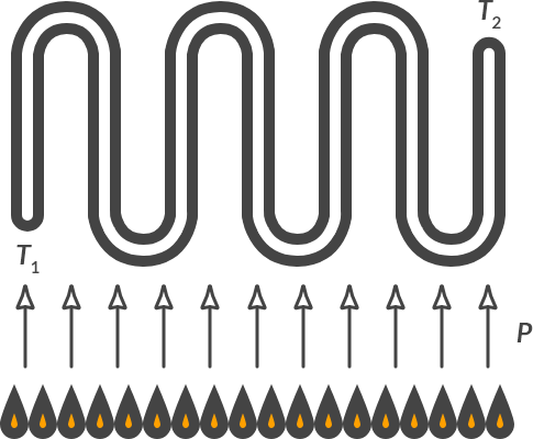
Fig. 4.9 Heat exchanger with heater flames.#
Which heat transfer mechanisms play a role here?
Solution
There is radiation: the tubes absorb heat by radiation from the flames. There is conduction: the pipes conduct the heat to the water. And there is convection: the hot combustion gases flow past the hot pipes and the hot pipes release heat to the flowing water.
How much heat is supplied to the flowing water per second?
Solution
\(0.75 \cdot 45\, \textrm{kJ} = 33.75 \,\textrm{kJ}\) is supplied to the water every second.
0.1 kg of cold water is supplied per second and 0.1 kg of heated water leaves the system. In other words: the mass flow rate is 0.1 kg/s. The total capacity of the heat exchanger pipe is 5 liters. Initially the water is 10 °C. What is the final temperature? What assumptions do you make to solve this easily?
Solution
A filled heat exchanger contains 5 kg of water. The total content of the heat exchanger heats up every second with:
After entry the water stays in the heat exchanger for \(m/\dot{m} = 5/0.1 = 50\) seconds. The final temperature of the water is therefore equal to:
Note
If you want more water per second (you increase the mass flow) and you do not increase the capacity of the burner, the temperature of the outgoing water drops! As soon as that heat exchanger rises in temperature, it will radiate heat itself to its (albeit also warm) environment!
4.5. Thermodynamics#
4.5.1. Ideal gas law#
For an ideal gas, the gas law can be deduced by conducting three experiments.
In the first experiment, a constant amount of gas in a cylinder is compressed by a pressure, while the temperature remains constant: isothermal compression.
In the second experiment, a constant amount of gas is heated in a cylinder while the pressure is kept constant: isobaric expansion.
In the third experiment, a constant amount of gas is heated in a cylinder, while the volume is kept constant: isochoric heating.
The three experiments are shown schematically in Fig. 4.10.
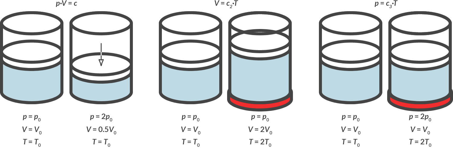
Fig. 4.10 Isothermal compression, isobaric heating, isochoric heating.#
From these three experiments, the following applies for each gas:
4.5.2. p-V-diagram#
In thermodynamics, it is common to display the state of the gas in a p-V diagram. In Fig. 4.11 the experiments of Fig. 4.10 are plotted in p-V diagrams. You see an isothermal (constant temperature), an isobaric (constant pressure) and an isochoric (constant volume) process, respectively.
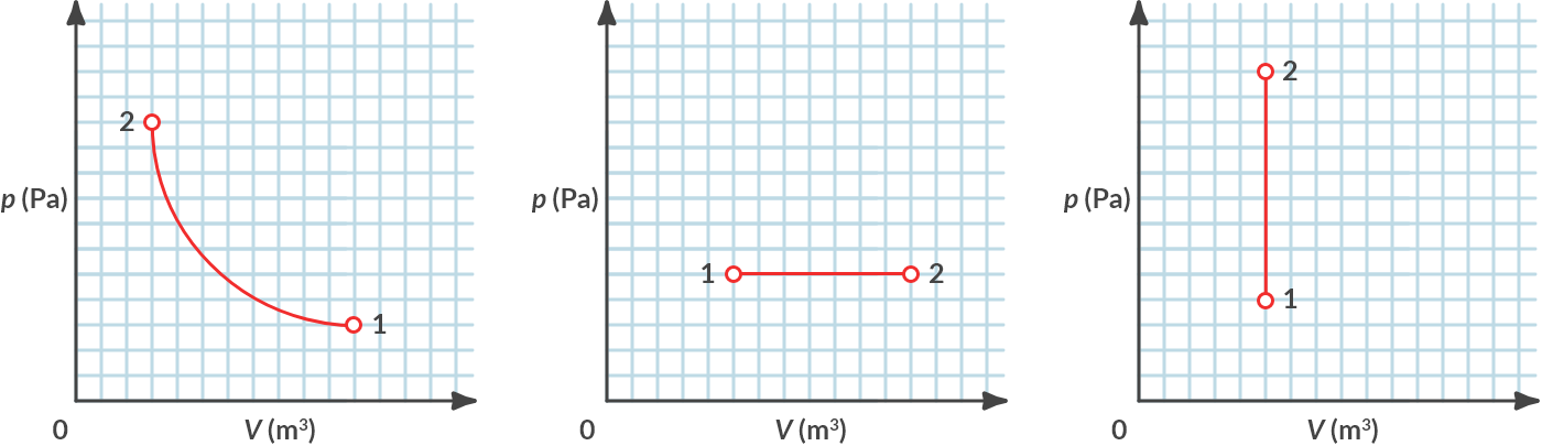
Fig. 4.11 (a) Isothermal, (b) isobaric, (c) isochoric.#
Note
By which relationships, which can be derived from (4.17), are these three graphs described?
4.6. Cyclic process#
A cyclic process is a process that consists of several process steps. For those process steps, it applies that after performing the final step, the state of the gas is again identical to the initial state. This applies, for example, to the processes of a cylinder of a (car) engine in which one has to deal with a compression step, a combustion step, an expansion step and an exchange change step. But a refrigerator also works that way; or a heat pump or a gas turbine. With a gas, the condition is determined by its temperature, its pressure and its volume. In a \(p-V\) diagram, therefore, a recycle process always forms a closed form.
Recycle process
A simple recycle process is shown in Fig. 4.12
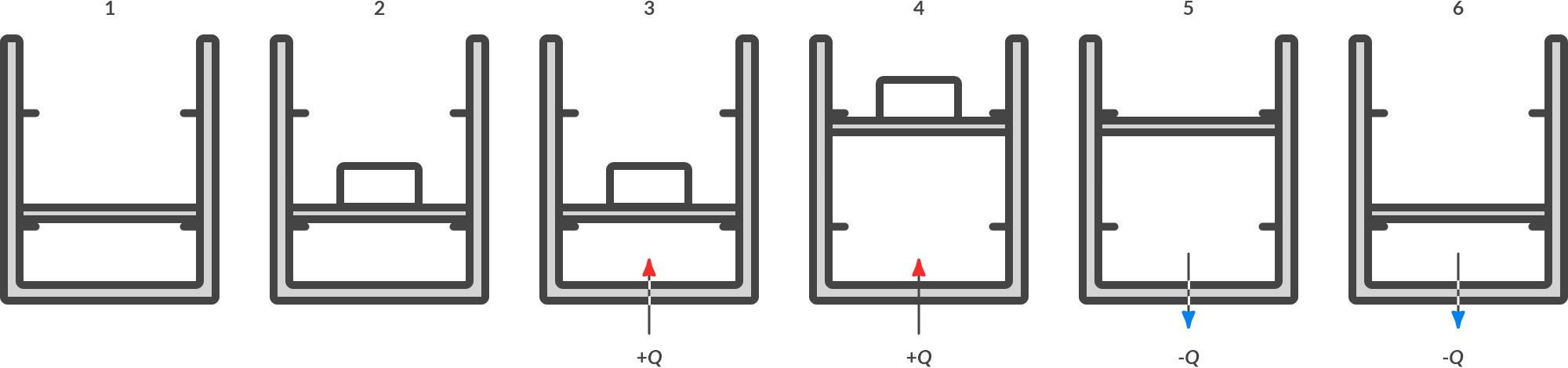
Fig. 4.12 Cyclic process.#
At the end of process 6, the state is identical to start state 1: this is called a cyclic process. The following happens during the circular process:
Process/state |
Description |
|---|---|
1 |
The piston lies quietly on the locking pins. |
1 \(\to\) 2 |
A box is placed on the piston. The piston rests on the locking pins. |
2 \(\to\) 3 |
Heat is supplied. The pressure increases until the gas pressure overcomes the load. The volume remains the same. |
3 \(\to\) 4 |
Heat is supplied. The pressure no longer increases, but the gas expands until the piston just presses against the upper locking pins. |
4 \(\to\) 5 |
The crate is taken away. The piston presses against the locking pins from below. |
5 \(\to\) 6 |
Heat is extracted from the gas. The pressure decreases until the pressure is just equal to the outside air pressure plus the pressure of the weight of the piston. |
6 \(\to\) 1 |
Heat is further extracted from the gas. The pressure no longer decreases, but the volume of the gas decreases. If the piston rests correctly on the locking pins, the heat dissipation will be stopped. |
If we plot this cycle process in a p-V diagram we get:
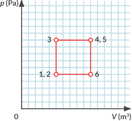
Fig. 4.13 \(p-V\)-diagram of the recycle process.#
4.6.1. Work of a gas#
In the cyclic process of Example 6 work is done in \(3\to4\). After all, a (constant) force is exerted over a distance traveled. This work is performed by the gas. The gas performs the following work:
If the force is not constant during the displacement, or if the pressure is not constant during the expansion of the gas, then the following applies to the work of the gas:
In a \(p-V\) diagram, this is equal to the area under the graph. If the volume of the gas increases, the gas performs positive work, if the volume decreases (then the gas counteracts), the gas performs negative work.
Work in a cyclic process
On which routes is work carried out by the gas in the cycle process of Example 6?
Is that negative or positive work?
Solution
The gas only performs work if it changes its volume. From \(3 \to 4\) the gas performs positive work (expansion), from \(5 \to 6\) the gas performs negative work (compression).
Work in a cyclic process (2)
Calculate the work done by the gas in the cycle of Fig. 4.3 (a). What is the net work per cycle that the gas delivers?
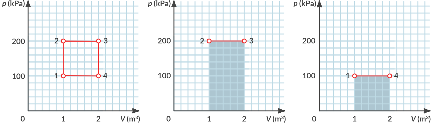
Fig. 4.14 (a) Cyclic process, (b) performed positive work, (c) performed negative work.#
Solution
From 2 to 3, the gas itself delivers positive work by expanding with the size of:
\(W_{2 \to 3} = p \cdot \Delta V = 200\, \textrm{kPa} \cdot (2-1)\, \textrm{m}^3= 200\, \textrm{kJ}\)
From 4 to 1 the gas performs negative work because it is compressed by the size of:
\(W_{2 \to 3} = 100\, \textrm{kPa} \cdot (1-2) [\textrm{m}^3]= -100 \, \textrm{kJ}\)
From 1 to 2 and from 3 to 4 are isochoric steps, the volume does not change, and the gas does not perform any work.
Overall, the gas performs in this cycle \(W_{\textrm{cycle}} = 200\, \textrm{kJ} - 100\, \textrm{kJ} = 100\, \textrm{kJ}\) net positive work.
In the case of heat machines, heat \(dQ\) is added (or extracted) from the device to the gas (or liquid) that flows through it. This heat is used on the one hand by the machine to perform work on the gas, but part of the heat is used to heat the gas, whereby the internal energy of the gas increases \(\textrm{dU} = m \cdot c_V \cdot \textrm{dT}\), where \(dT\) is the temperature increase and \(c_V\) the specific heat at constant volume. This is the specific heat of a gas if the gas is kept in a constant volume. The following applies as result of energy conservation:
This comparison is known as the first law of thermodynamics. Not all heat \(dQ\) that is added or withdrawn from the system can be efficiently converted into work \(dW\).
4.7. What lies ahead#
In this chapter you have become acquainted with energy storage and energy transport. You can use the theory that you have learned here to make an initial estimate of heat storage and heat transfer processes. Heat transfer via convection has not yet been discussed in detail but will be discussed extensively in the remainder of the curriculum. Convection plays an important role in the development of heat exchangers, for example. All kinds of design choices (material, pipe diameter, pipe roughness) all influence the heat transfer. These design choices also influence the choice of pumps that the media must pump through the heat exchanger. The field of energy technology is closely linked to the field of process engineering constructions (liquids and flow) and combustion technology.
4.8. Problems#
For the following exercises use symbols as long as possible and only in the end fill in the values given.
Exercise 4.1 (Heat transfer in a coffee machine)
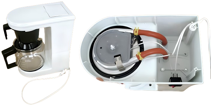
Fig. 4.15 Coffee machine (left), internals viewed from below (right).#
We will look at a coffee machine as depicted in Fig. 4.15 on the left and its internals as shown in Fig. 4.15 on the right. This coffee machine has an electrical power of \(1100\) W. There is an electric heating element in the base, which heats the water through a metal tube. It takes \(3\) minutes and \(1\)0 seconds to make \(350\) ml of coffee. This means that the water passes through the heating element at a flow rate of \(1.8 \textrm{ cm}^3/\textrm{s}\). The cold tap water is heated from \(10\, °\textrm{C}\) to \( 90\, °\textrm{C}\). Water has a specific heat of \(4180 \textrm{ J}/\textrm{(kgK)}\) and a density of \(1000 \textrm{ kg}/\textrm{m}^3\).
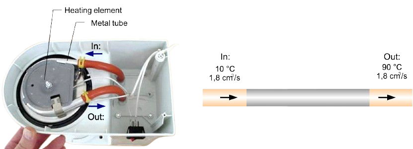
Fig. 4.16 Internals base of a coffee machine (left), in- and outflow water (right).#
Calculate the (average) power that is transferred by the heating element and the metal pipe to the water.
In addition to the water, the heating element also heats the hotplate. We perform an experiment and place a cylindrical glass jar, with a glass bottom and lid, on the hotplate. This glass jar has an internal diameter of \(10\) cm, a height of \(12\) cm and a glass thickness of \(4\) mm.
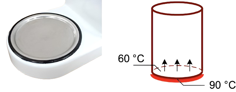
Fig. 4.17 Hotplate (left), coffee jar including temperatures (right).#
At a given moment we measure the temperature at the bottom of the pot, on both the inside and outside. The glass on the inside of the pot has a temperature of \(60\, °\textrm{C}\). The glass on the outside near the heating plate is at a temperature of \(90\, °\textrm{C}\). Glass has an emission factor of \(0.92\) [-] and a thermal conduction coefficient of \(0.80 \textrm{ W}/\textrm{(m K)}\).
Compute the amount of heat that is transferred per second via conduction through the bottom of the cylinder.
After some time, thermal equilibrium is established. The coffee jar is at a constant temperature in time. We assume, see Fig. 4.18:
The inside wall of the jar has a single internal temperature \(T_i\).
The outside wall has a single external temperature \(T_b\), the only exception is the bottom.
The bottom has a temperature equal to the heating plate: \(90\, °\textrm{C}\).
The ambient temperature is \(20\, °\textrm{C}\).

Fig. 4.18 Jar including the temperature assumptions.#
We assume that all heat loss from the jar goes through the sides and the top. The questions below distinguish between: radiation, conduction, and convection. Work as much as possible parametrically with the given symbols, without their number value.
Express the heat per second lost to the environment due to radiation in terms of \(T_b\).
Express the heat per second transferred trough the jar walls, sides and top, due to conduction in terms of \(T_b\) and \(T_i\).
Compute the temperature \(T_i\) on the inside walls of the jar, when the outside wall has a temperature of \(60\, °\textrm{C}\).
Compute the heat lost to the environment per second due to convection, when the outside wall has a temperature of \(60\, °\textrm{C}\).
Context
Heat is present everywhere in our environment, such as the heat in the outside air, the surface water or the soil. However, this heat cannot be used immediately because the temperature is too low. With a heat pump, it is possible to efficiently upgrade this heat to a suitable temperature level. Just as a water pump can pump water from a low to a high level, a heat pump “pumps” heat from a low to a high-temperature level. An example of such a heat pump is present in the Geohuis of the TU/e. The Geohuis is a building in which installations for climate control can be installed. With the aid of the available measuring instruments, these installations can be analyzed for their performance. Current testing facilities include a heat pump in which energy from the environment is ‘pumped up’ to higher temperatures for heating purposes.
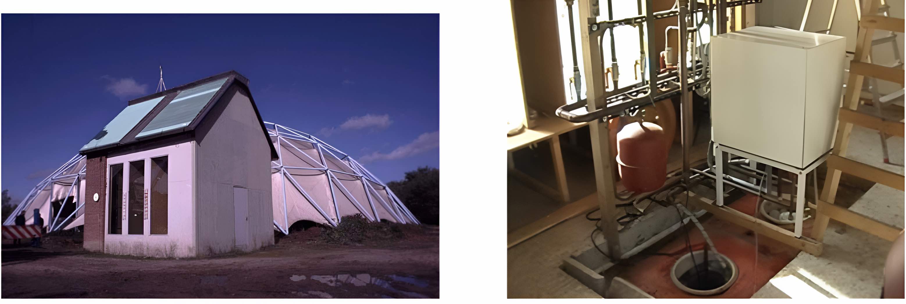
Fig. 4.19 The Geohuis in the DUBO-park at the TU/e (left), the heat pump at the Geohuis (right).#
The heat pump
There are many different types of heat pumps, but the method of operation is always the same. The process of a heat pump can be divided into four steps:
\(1\rightarrow 2\) A liquid with a boiling point lower than the temperature of the environment temperature is used for the transportation of heat. This liquid evaporates under the influence of the heat from the environment. This way, heat is extracted from the environment by the evaporating liquid. (This phenomenon can also be observed with a spray can for, for example, deodorant or hair spray, which gets cold if used).
\(2\rightarrow 3\) The vapor is then compressed by a compressor. This increases the temperature and pressure of the vapor. (This phenomenon can also be observed when inflating a bicycle tire, where the bottom of the pump can get very hot.) Because the pressure has increased, the temperature of the boiling point has also increased (think of a pressure cooker).
\(3\rightarrow 4\) . The vapor then condenses into a liquid, releasing heat. The heat released is usable because the temperature is higher than in the first step. As an example, this heat can be used for central heating.
\(4\rightarrow 1\) Finally, the liquid flows via a thermal expansion valve in which the pressure and temperature are lowered back to the evaporator. At the evaporator, the process starts all over again.
Exercise 4.2 (COP of a heat pump)
We have the following characteristics of a new heat pump, see Fig. 4.20. We want to determine the COP from this.
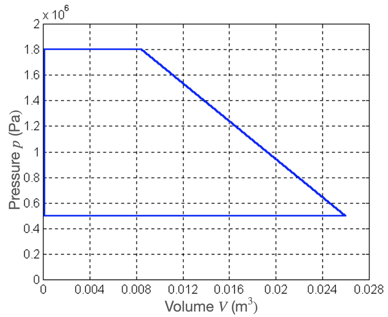
Fig. 4.20 \(p-V\) diagram of a heat pump.#
Using the p-V-diagram, calculate the required energy that has to be supplied to the pump, to complete a single cycle of the p-V-diagram. We agree: the lower-left point is \(A\) and that we go with the clock trough \(B, C,\) and \(D\).
For the ideal case, in which no heat is lost during the compression and expansion step, the Coefficient of Performance (COP) is provided by
Parameters |
|
|---|---|
\(Q_h\) |
The useable heat released by the heat pump in [J]. |
W |
The energy required to drive the heat pump in [J]. |
From measurements, it is found that a heat pump delivers \(75.0\) kJ of heat (\(Q_h\)) per cycle.
Compute the COP of this heat pump
Assume that a single cycle takes \(20\) seconds. How much energy would then be produced per hour?
How much energy do you save if you assume that only the supply of energy to drive the heat pump is required?
Exercise 4.3 (Heat and cold storage of Gemini)
On a cold winters’ day, it is a freezing \(-10\, °C\) outside. To still maintain the temperature inside Gemini South at a comfortable \(22 °C\), \(450\) kW of energy needs to be supplied.
In Gemini South \(500\) computers test and printers reside, each uses an average of \(200\) W of energy. Normally around \(75\%\) of these devices are turned on. Furthermore, on this cold winter day, the lights burn brightly. In total, all these lights produce a heat equal to \(200\) kW. We would like to know how much energy can be saved by a heat pump.
How much energy is produced by computer, printers, and lights?
How much energy does the heating need to supply to Gemini South, such that it is maintained at a comfortable temperature?
Assume that a heat pump is installed with \(\textrm{COP} = 3.5\) and that \(100\%\) of the energy by the devices is transferred to the environment.
How much energy must be supplied to the heat pump such that enough heat is delivered to Gemini South?
How much energy can you save if you would make use of heat and cold storage?
Exercise 4.4 (Rectile heating)
Reconsider the reticle stage inside a wafer stepper from Exercise 3.5. The reticle is directly exposed to intense radiation (EUV light) which is partially absorbed and heats up the reticle. Suppose the absorbed heat-load is equal to \(25\, \textrm{W}\) distributed over a surface area of \(104 \times 132\, \textrm{mm}\) (spot size EUV light beam). The cooling water had a fixed temperature of \(22 ^\circ\textrm{C}\). The reticle is made from ZeroDur, which has a thermal conductivity of \(k = 1.46\, \textrm{W}/(\textrm{m} \cdot \textrm{K})\) and a thickness equal to \(6.35\, \textrm{mm}\).
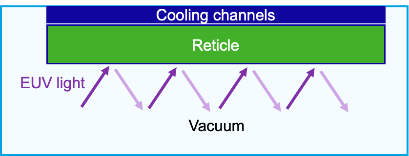
Fig. 4.21 Schematic cross-sectional view of the reticle heating/cooling setup, showing the reticle clamped under cooling channels, with EUV light passing through and reflecting in vacuum.#
What will be the surface temperature of the reticle? You can assume steady state and only have to take into account heat loss to the cooling channels.
Assume a coolant flow of 3 liter/min, what would be the outlet temperature of the coolant in steady state (assuming an inlet temperature of \(22 ^\circ\textrm{C}\)).
In reality, the reticle also loses some heat to the environment. Suppore ZerDur has an emission factor of \(\epsilon = 0.92\) and a heat transfer coefficient (due to the rarified hydrogen gas in the “vacuum“ environment) of \(1\, \textrm{W}/(\textrm{m}^2\cdot K)\). Taking into account these heat losses as well, what would be the new surface temperature of the reticle?
How efficient is the coolant at removing the heat (meaning which percentage of the absorbed heat is removed via the active cooling)